The Voyager program involved sending two space probes, Voyager 1 an...
Here are a few images of Neptune taken by Voyager 2
*Neptune Ful...
Voyager was the first of a class of NASA spacecrafts that could be ...
The **Deep Space Network (DSN)** is NASA’s international array of g...
Voyager took photographs in black and white. Color images were reco...
**Pioneer 10** and its twin probe, **Pioneer 11**, were the first N...
Sputnik 1 (the first satellite to orbit the earth) carried two radi...
### Elevation Angle
This is “up” and “down” angle from a reference...
**EIRP** (Effective Isotropic Radiated Power) is the measured radia...
**Convolutional codes** are a type of error-correcting codes. In ot...
*Diagram of Voyager’s High Gain Antenna*

Vovager
Firsts
Mission Telecommunication
Edward
C.
Posner
Lawrence
L.
Rauch
Boyd
D.
Madsen
1
HIS
ARTICLE TELLS ABOUT
THE
COMMUNICATIONS
firsts of the National Aeronautics and Space Administration’s
(NASA’s) Voyager mission. This dual-spacecraft mission to
Jupiter. Saturn. Uranus, Neptune, and their moons and rings
was launched in 1977 and completed its planetary phase some
I7
years later with the Voyager
2
Neptune encounter in August
1989 (see Figure
I).
Although the spacecraft hardware repre-
sents early 1970s technology (see Figure
2),
the absolutely out-
standing system design included computer control of almost
all spacecraft ar?d instrument functions. This provided the
flexibility for recovering from a wide range of malfunctions.
The potential was also created to effectively almost redesign
the spacecraft and its instrument data systems in flight via
uplinked software (a first) to take advantage of post-launch-
developed technology (such as image compression) and also of
new requirements developed later in the mission. This was es-
pecially valuable because the original mission commitment
did not include Uranus
or
Neptune.
Half of the Voyager telecommunication system
is
located
on Earth (downlink receiver and uplink transmitter). For the
better part of a decade and a half after the spacecraft hardware
design was frozen, the technology of the ground system could
continue to develop to meet the needs associated with steadily
decreasing received signal strength and also to improve naviga-
tion techniques in the face of the increasing round-trip light
time to the spacecraft. Significant parts of the ground-system
technology in use for the Uranus and Neptune encounters were
simply unavailable when the spacecraft was launched. The
ground system is embodied in the Deep Space Network (DSN),
which the Jet Propulsion Laboratory (JPL) develops and oper-
ates for NASA’s Office of Space Operations. JPL designed and
built the two Voyager spacecraft for NASA’s Office of Space
Science and Applications.
This technology flexibility in both the Voyager spacecraft
and ground systems enabled a mission which, along its way to
becoming a truly remarkable success, established many firsts
associated with its telecommunication system. Ofcourse no as-
This article represents the results
of
one phase of research carried out
at the Jet Propulsion Laboratory, California Institute of Technology,
sponsored
by
the National Aeronautics and Space Administration.
22
September
1990
-
IEEE
Communications Magazine
Fig.
1.
Blue Neptune. Color image ofNeptune taken by Voyager
2
when
it was
7
inillion
kin
(4.4
million miles) from Neptune’s surface. The
Great Dark Spot is visible in the center, accompanied by white
high-altitude clouds. Two color.filters (green and orange) were used, and
about
2
inillion hits were sent,for each ,filter, totalling almost
4
million
hits.
pect of a deep-space mission would be possible without tele-
communication, but by “telecommunication firsts” we mean
first-time accomplishments specifically relating to
or
interact-
ing with the telecommunication system.
Radio
Telemetry
The two Voyager spacecraft were not the first to send imag-
es from Jupiter and Saturn, nor the first to leave the
solar
system-these records belong to the Pioneer
10
and
1
1
space-
0
163-6804/90/0009-0022 $01
.OO
a
1990
IEEE

craft, built by TRW for the Pioneer project at NASA’s Ames
Research Center. However, the Voyager spacecraft, built and
managed by JPL for NASA, have much larger downlink data-
rate capability at all distances due to their 20 W transmitters
and larger 3.66 m antennas (a deep-space first) with X-band
downlink frequency (a deep-space first) providing an antenna
gain of 48.2 dB. The resulting largest ever Effective Isotropic
Radiated Power (EIRP) of 1.32 MW from deep space permit-
ted the transmission of almost
80,000
high-resolution images
during the mission; the current runner-up is the Mars Viking
dual orbitedlander mission
(1
976 encounter) with almost
60,000 images. Actually, the Voyager cameras had about
97,000 shutter activations-some exposures were not trans-
mitted and others were combined to form color images.
The Voyager two-spacecraft mission also holds the records
for the most planets visited (4), most bodies imaged (58, count-
ing the four ring sets around the four target planets, as well as
Earth and its moon), and the most data bits (about 200 Gb)
transmitted from deep space over the life of a mission. This last
record, however, is expected to be bested by the end of the
Magellan prime mission, a radar mapper of Venus which went
into Venus orbit on August
IO,
1990.
The Voyager Uranus (January 1986) and Neptune encoun-
ters established at those times the records for the most distant
image transmission ever, 2.75 billion miles from Neptune. The
data rate of 2 1,600 b/s from Neptune established a record for
the largest distance-normalized data rate, 4.2E23 (b/s
x
km2).
For example, at synchronous Earth satellite altitude this would
give a data rate of greater than
1
E 14 b/s. Because of the wide
range of distances for the Voyager mission, the spacecraft
made use of the largest array of data rates of any deep-space
mission (and probably of any space mission, but this is hard to
check). In addition to the 2 1,600 b/s rate, rates from 40 b/s to
1
15,200
b/s were used by the Voyagers at various times, for a
total of
28
telemetry rates.
Other firsts for the Voyager spacecraft radio hardware in-
clude the dual X-band&-band
(8.5
GHz/2 GHz) antenna feed
(see Figure 3) with the former providing left- as well as right-
hand circular polarization to rely on polarization isolation in-
stead of on less reliable antenna switches for the two X-band
transmitters. There was also the first use of RF channel selec-
tion by a spacecraft (the X-band channels numbered 14 and
18), and the first use of modulation index selection, including
the possibility of fully suppressed carrier. This was used not for
telemetry but in connection with “delta Very Long Baseline
Interferometry (VLBI)” for radio navigation’ (see Figure 4),
another first.
The spacecraft transponder provided the first use of the
two-way non-coherent mode and the subcarriers were
selectable. There were two power amplifiers for X-band and
two for S-band with one of the latter two being a solid-state am-
plifier (a deep-space first). The spacecraft transponder also in-
cluded the most stable oscillator (2 parts in lE12 over
100
s,
aptly named the Ultra-Stable Oscillator-USO) ever yet used
in deep space, and at the time the best in space (GPS cesium de-
vices are now an order of magnitude better), as well as the first
application of a Surface Acoustic Wave (SAW) filter in deep
space, used in the transponder multiplier chain.
‘The direction of a spacecraft with respect to the baseline between
two DSN antennas is determined by measuring the time difference be-
tween the two one-way paths from the spacecraft to the antennas.
To
do this, the spacecraft transmits a wideband signal (in this case the
telernetering signal was used). The signals from the two antennas are
cross-correlated. The “delta”
in
“delta VLBI” refers
to
the procedure
whereby the system is calibrated in real time by alternately observing
both the spacecraft and some directionally nearby quasar that is part of
a quasar “grid.” The grid was very accurately determined over
a
long
period of time by ordinary VLBI. This navigation application of VLBI
is
often called “delta Differenced One-way Ranging (DOR).”
The Earth-based part of the Voyager telecommunication
system also achieved many firsts. The three 70-m DSN anten-
nas have the lowest ever system noise temperature of an opera-
tional X-band (8.5 GHz) receiving system for space
or
any
other X-band communication-20.9 Kat 90 degrees elevation
and 25.5
K
at 30 degrees elevation (in clear dry weather). The
same antennas provided the first operational use of hydropho-
bic coating on feedhorn covers to mitigate weather-dependent
microwave system noise increase during rain. Also, for the
Voyager mission, the DSN made the most advanced and deli-
cate use of multisite weather probability estimates to improve
weather-dependent X-band performance during rain. The
X-band arraying of the National Science Foundation/National
Radio Astronomy Observatory’s (NSFINRAO’s) Very Large
Array (VLA) in New Mexico with the 70 m and 34 m antennas
at the Goldstone Complex for the Neptune encounter involved
the first operational space use of High Electron Mobility Tran-
sistor (HEMT) amplifiers; these were at each ofthe 27 VLA an-
tennas.
This arraying with the VLA (see Figure
5)
established a
number of records: the most antennas (29) ever arrayed any-
where at once (27 VLA plus 2 at Goldstone); the largest fully-
steerable equivalent aperture
(1
5
1
m) ever used for a commu-
nications link (the overall record belongs to the Cornell-
Arecibo 300-m antenna used for the S-band International
Cometary Explorer in 1985, but the Arecibo antenna is not
fully steerable).
Also, the VLA arraying was the longest (aperture separa-
tion) array- 1,200 miles-ever used for communications, or,
in real time, for anything else. The prior record was Canberra/
Parkes for Voyager Uranus, 200 miles via ground microwave
link; Parkes, a 64-m antenna, is operated by the Australian
Commonwealth Scientific and Industrial Research Organiza-
tion (CSIRO). Finally, this was the first arraying for telemetry
via satellite (real-time VLA to Goldstone; see Figure 6).
The 70 m antenna at the DSN Goldstone complex had the
highest power operational coherent uplink for spacecraft-up
to 400 kW Continuous Wave (CW) at S-band. During the mis-
sion, this was used with a margin of
5
dB. That was the highest
EIRP communications transmission ever, about 200 GW.
The Voyager downlink EIRP of 1.32 MW from the Neptune
distance of 4.42E9 km gives a power flux density of 5.38E-2
1
W/m2 at Earth receiving stations. At the data rate of 2 1,600
ds,
this is an energy per bit flux density of 2.49E-25 (J/b)/(m2) at
the receiving stations-far smaller than ever before used any-
where for operational radio
or
any other communication.
Early in the mission, one of the Voyager 2 radio receivers
failed completely. The other had a capacitor short circuit in the
filter of the carrier phase-locked loop which very greatly re-
duced the lock-in frequency range. This greatly reduced lock-in
range was much smaller than the loop oscillator’s drift due to
such things as spacecraft temperature change. Yet it was possi-
ble to maintain the full command function of the impaired re-
ceiver by creating the first continuous frequency-pro-
grammable uplink, derived originally from DSN planetary
radar. The programmed frequency was obtained from a model
for the spacecraft frequency drift.
Coding
During the entire mission, the telemetry downlink channel
code was the NASA Standard constraint-length 7, rate 1/2
convolutional code using a real-time hardware Viterbi decoder
(first space-based short-constraint-length convolutional code
Viterbi decoded) at each receiving station. For the Voyager Ju-
piter and Saturn encounters, uncompressed image data was
sent directly over the convolutionally coded channel. This pro-
vided the required bit error probably of 5E-3 at a zero-margin
signal-to-noise ratio E,/N, of 2.34 dB, the lowest anywhere
ever, as was hinted in the previous section. Other science data
September
1990
-
IEEE
Communications Magazine
23

Scan
Imaging
(ISS),
Narrow An
and Radiometer
Low-Energy Charged Particle
Hydrazine Thrusters
(1
6)
for Attitude Control and
(Not All Shown
in This View)
High-Gain Antenna Trajectory Correction
(HGA)
(3
7
m DIA)
Shunt Radiator
Canopus Star Tracker
(2)
(Not Visible in This View)
Astronomy (PRA) and
Plasma Wave (PWS)
Voyager Spacecraft
(Note Shown Without Thermal
Blankets for Clarity)
Fig.
2.
Voyager spacecraft. The subsystems are shown
by
callout. The
3.66
m
diameter antenna is a
high1.v visible feature.
Fig.
3.
Dual X/Sspacecraft antenna with feeds. The feed
on
the tripod is
the S-band.feed, while the dual-polarization X-band feed is located
on
the reflector itse&
Quasar
Spacecraft
Fig
4.
Delta
VLBI
concept. For Voyager
2
on
its way to Neptune, the
tvpical angular distance between the quasar used and Voyager
2
was
15
degrees, providing
150
nrad spacecraft angular positron accuracy.
24
September
1990
-
IEEE
Communications Magazine

Fig.
5.
Interagency arraying. World map showing antenna facilities used to support Voyager
2
at Neptune. Insets
show
pictures
of
the
antennas used, including the
27
VLA
antennas in a Y-configuration. The
VLA
antennas are
on
rails: the closest configuration was used
because the resolution
of
the
VLA
was not required.
only
the aperture,
27
x
2Sm
antennas, equivalent in aperture to a single
130
in-diameter antenna.
at key times used a concatenated Golay (24,12) outer code
(also a space first) to provide a bit error probability of 1 E-5, but
at
3
dB higher signal-to-noise ratio per information bit.
Beginning with the Uranus encounter, an outer Reed-
Solomon code (see Figure
7)
was applied to the X-band link,
using the by now NASA Standard 16-symbol-error-correcting
8-bit (255,223) Reed-Solomon code with “interleaving depth
4” (a deep-space first), with a hardware encoder included in the
spacecraft. The inner code remained the
7,
1/2 convolutional
code. The Reed-Solomon encoder was originally included on
the spacecraft for compatibility with image compression,
which needs low error probability but efficient power use. The
encoder was available at launch, but the corresponding ground
decoder was available only later, in time for the 1986 Uranus
encounter. This improved concatenated coding scheme pro-
vides a bit error probability of
1
E-6 with a theoretical signal-to-
noise ratio E /No of 2.43 dB. The additional radio loss in-
creased this kgure to somewhere between 2.5 and 3.0 dB
depending on how well a station was tweeked up. Since the
Shannon limit for unrestricted bandwidth is -1.59 dB, this per-
formance is within 4.02 dB of the Shannon limit,* the closest
anywhere for this low error probability.
The low error probability provided by the concatenated
Reed-Solomon/convolutional
coding enabled the use of a
lossless image-compression algorithm (a deep-space first-
about a compression factor of 2.5) which was not available at
the beginning of the mission. One of the spacecraft backup
computers was assigned to carry out the data compression al-
gorithm via software which was uplinked to the spacecraft.
This was a very important contribution to the high imaging
rates achieved at Neptune. The algorithm was essentially a uni-
versal source code on the differences between successive pixels
on a scan line.
Navigation
The navigation capability provided by the Voyager radio
system also resulted in a number of firsts. The Neptune en-
counter was supported by the longest-distance ranging ever,
doppler, and the first operational use of delta
VLBI.
The rang-
2The bandwidth expansion factor due only to the coding is
2
x
2551
223
=
2.29.
For this, the Shannon limit is
-0.21
dB. However, the
convolutionally coded signal is modulated on a square-wave
subcamer, containing at least the third harmonic, which is in turn
phase modulated (with double sidebands) on the X-band carrier.
These modulation processes increase the bandwidth expansion factor
perhaps six times beyond that due to coding. The result is a Shannon
limit only a little larger
(0.2
dB) than that for unrestricted bandwidth.
Also,
the Shannon limit should be increased slightly for the nonzero
error probability, which is why this is closer to its Shannon limit than
the unconcatenated
SE-3
transmission was (by
0.1
dB).
September
1990
-
IEEE
Communications Magazine
25

Fig.
6.
Real-time arraying. Artist’s sketch showing real-time telemetry arraying
of
the
VU
with Goldstone via satellite.
ing accuracy was about one m in 4.42E9 km-the most accu-
rate space distance measurement (percentagewise) ever made.
The doppler provided an accuracy of about one millimeter per
second. The first operational delta VLBI provided an angular
accuracy of 150 nanoradians. The Voyager mission used the
first three-way ranging ~ystem,~ which was made necessary by
round-trip light times too long for the pass over a single station.
This navigation accuracy allowed the closest encounter ever
with a planet-within
3,000
km of Neptune’s sensible atmo-
sphere, within 500 km of the burn-up danger zone. This per-
mitted a 50-degree trajectory bend for the Triton encounter.
Including the use of spacecraft-provided images, the overall
navigation accuracy relative to Neptune was about
40
km.
Voyager was also the first space project to make operational
use of ground-based hydrogen masers for radio navigation,
whose excruciating stability of
1
E-
14 over part of a day is nec-
essary for two-way doppler and ranging at these long round-
trip light times. Also, for the Neptune encounter, the hydrogen
3The prior two-way ranging system measured the round-trip light
time between an Earth station and the spacecraft by transmitting a sig-
nal to the spacecraft, which coherently shifts the frequency and trans-
mits back to the Earth station, where the received signal is correlated
with the signal being transmitted. This requires that the spacecraft
be
in good view of the Earth station
for
a significantly longer time than the
round-trip light time-which becomes impossible near the limits of
the solar system. The three-way ranging system transmits the signal
from one Earth station and receives the transponded signal from the
spacecraft at another Earth station which is next coming into view, typ-
ically some eight hours later. This received signal is stored for later cor-
relation with the (stored) transmitted signal.
masers in the DSN were synchronized absolutely within
1
ps,
an operational record.
Radio Science
In the radio science area, where the medium is the message
(see Figure
8),
the Voyager mission achieved a number of
firsts. It was the first mission specifically designed to obtain
radio-science data-by having very exacting requirements for
radio system stability, both at
S-
and X-bands, and for frequen-
cy and timing system stability, both flight and ground.
At Neptune, Voyager carried out the longest-distance Radio
Frequency
(RF)
probe of a medium and used the first array of
ground antennas for radio science, Canberra and Usuda (Japa-
nese Institute of Space and Astronautical Sciences, ISAS) at
S-band (non-real-time).
To
meet the exacting radio science re-
quirements for Voyager, the hydrogen masers in the DSN were
modified to reduce their phase noise at X-band by
10
to
20
dB-to -54 dBc at
1
Hz and
-60
dBc from
IO
to 10,000
Hz.
Navigation requires good long-term timing-system stability
(over several hours), expressed as an “Allan deviation” of
1
E-
14 in units of cycles/cycle. But radio-science probing of the me-
dium also requires the very good short-term stability expressed
above in terms of phase noise.
Epilogue
The really remarkable success
of
the Voyager mission, both
from the system reliability and science data aspects, is firmly
based
on
an absolutely outstanding systems design exploited to
its utmost limits by truly dedicated operational and science
teams supported over an extended period by NASA. The vari-
26
September
I990
-
IEEE Communications Magazine

Fig.
7.
Concatenated convolutional coding concept. The inner code, the constraint-length
7
rate
112
NASA Standard
convolutional code, is the one encoded last
on
the spacecraft and decoded first (via Viterbi decoding using
soft
decisions)
on
the ground. The outer Reed-Solomon code encodes the entire data stream. which is then fed to the
spacecraft convolutional encoder.
ous communication firsts and records described above are
both a cause
for
and a natural product of this winning combi-
nation.
Acknowledgments
The Voyager project and the DSN are managed by JPL
of
the California Institute of Technology under contract with
\
\
\
K>-
\
,
-
,
\
'
\\
Neptune
11
Detect0
Signal
and Sampling
r Conditioning Recc,
\
Fig.
8.
Radio Science. Geometry of Voyager
2
at Neptunefor the Triton
occultation. The radio wave traverses the atmosphere and ionosphere
of
Triton. From eflecls observable in the amplitude and phase as received
b.v
a dedicated open loop radio science receiver. finely detailed
conclusions about Triton were drawn.
NASA. The Bendix Field Engineering Corporation operates
the DSN Goldstone complex under contract to JPL. The
Madrid Complex is operated by a Spanish government agency,
Instituto Nacional de Technica Aerospacial (INTA), while the
Canberra complex
is
operated by the Australian Space Office
(ASO).
The authors would like to thank their JPL associates H. W.
Baugh, J.
S.
Border,
H.
G.
Cox, A. W. Kermode, P.
F.
Kuhnle,
F. Pollara, L. Swanson,
G.
P.
Textor, and J. A. Wackley
for
counsel on Voyager firsts and records.
References
[l] Edward C Posner and Robertson Stevens, "Deep Space
Communication-Past, Present, and Future," I€€€ Commun
Mag
,
vol 22, no 5, pp 8-21, May 1984
"Voyager 2 at Neptune and Triton," editorial and twelve articles,
So-
enceMag
.voI 246,no 4,936,~~ 1,369andpp
1,417-1,501,Dec
15, 1989
[2]
Biography
Edward
C.
Posner (F) is Chief Telecommunications and Data Acquisition
Technologist at the California Institute of Technology's (Caltech's) JPL and
Visiting Professor of Electrical Engineering at Caltech. He has been associated
with deep space communication and the DSN since 1960, when he began con-
sulting at JPL before accepting a position there, and before the DSN had its
present name. This is his third article for /€€€Communications Magazine. In ad-
dition, Posner was Guest Editor of the November 1989 special issue on 'Neur-
al Networks in Communication."
Lawrence
L.
Rauch (LF) is Senior Research Engineer (Retired) at Caltech's
JPL as well as Professor Emeritus of Aerospace Engineering at the University
of Michigan. In addition, he taught in Caltech's Electrical Engineering Depart-
ment for eight years after retiring from Michigan, while he was Telecommuni-
cations Science and Engineering Division Technologist at JPL. Rauch is one of
the founders of radio telemetry, his landmark book
Radio
Telemetry-co-
authored with Myron Nichols-having appeared in 1952 and subsequently
having been translated into Japanese and Russian.
He
maintains an active re-
search interest in the phase tracking of weak radio signals and consults for
JPL's Telecommunications and Data Acquisition Office.
Boyd
D.
Madsen is a 1960 graduate of Brigham Young University with a
B.E.S. in electrical engineering. He joined the Voyager Project in 1974 after
working on the Mariner Venus-Mercury mission.
He
has thus been involved
with Voyager Telecommunications at JPL since three years before launch.
He
joined Galileo in 1979 and Magellan in 1986.
He
is currently the Technical
Group Supervisor of the Voyager-Galileo-Magellan Telecommunications Sys-
tems Group in JPL's Telecommunication Science and Engineering Division.
These are the three major JPL deep-space flight projects currently flying.
September
1990
-
IEEE
Communications Magazine
27
Voyager took photographs in black and white. Color images were reconstructed by making a computer composite of three black and white images taken through orange, green, and violet filters.
**Convolutional codes** are a type of error-correcting codes. In other words, they provide you with a way of encoding a message you want to send so that it is resistant (to an extent) to errors that might be introduced by noise. If you wish to learn more about convolutional codes I suggest you read [chapter 7 of MIT’s Digital Communication Systems class notes](https://ocw.mit.edu/courses/electrical-engineering-and-computer-science/6-02-introduction-to-eecs-ii-digital-communication-systems-fall-2012/readings/MIT6_02F12_chap07.pdf).
*Diagram of Voyager’s High Gain Antenna*

**MASER** (acronym for Microwave Amplification by Stimulated Emission of Radiation) is a device that produces coherent electromagnetic waves through amplification by stimulated emission. A LASER is a MASER that works with higher frequency photons in the ultraviolet or visible light spectrum. A hydrogen maser, also known as hydrogen frequency standard, is a specific type of maser that uses the intrinsic properties of the hydrogen atom to serve as a precision frequency reference.
### Elevation Angle
This is “up” and “down” angle from a reference plane, generally the horizon.

### Noise Temperature
The noise in a system can be expressed as an equivalent noise temperature. Higher noise in the system would mean a higher noise temperature.
The reason why “temperature" is used is because of *thermal noise*. A higher temperature means that the electrons in the medium are moving around more and therefore generate observable noise. For most noise processes you can express them (at least in part) by an equivalent thermal noise.
**EIRP** (Effective Isotropic Radiated Power) is the measured radiated power of an antenna in a specific direction.
Sputnik 1 (the first satellite to orbit the earth) carried two radio beacons on frequencies of 20MHz and 40MHz. At these frequencies, amateur radio enthusiasts could easily tune into its transmissions as it passed overhead (you can listen to samples [here](https://www.youtube.com/watch?v=-YSm2qFwRpI) ). The Explorer earth orbiter missions used VHF (~100MHz). The first Lunar probe (Pioneer III) used UHF (960MHz). Over time the tendency was to increase the frequency, first to S-band (2.3 GHz) and then to X-Band (8.4GHz). The two main reasons for this was competition for frequency allocations at lower frequencies (the frequencies you can use to communicate with are tightly regulated) and the need for more spacecraft antenna directivity.
**Pioneer 10** and its twin probe, **Pioneer 11**, were the first NASA space probes to be designed for exploring the outer Solar System. Launched in 1972 and 1973 respectively they ended up serving as a fantastic preparation for the Voyager mission. The initial goals of the Pioneer program were:
Explore the interplanetary medium beyond the orbit of Mars
Investigate the nature of the asteroid belt from the scientific standpoint and assess the belt's possible hazard to missions to the outer planets
Explore the environment of Jupiter
Later on, the planning for the encounter with Saturn added more goals.
*Pioneer 10 image of Jupiter*

*Artist rendition of the Pioneer 10 space craft at Jupiter*
The Voyager program involved sending two space probes, Voyager 1 and Voyager 2 to study the outer solar system. Both probes were launched in 1977 ( Voyager 2 was actually launched before Voyager 1) within the 3 year period that occurs once every 176 years when a unique alignment of Earth, Jupiter, Saturn, Uranus and Neptune presents the opportunity for a “grand tour”. Only Voyager 2 would go on to explore the planets beyond Saturn.

*Voyager flight paths*
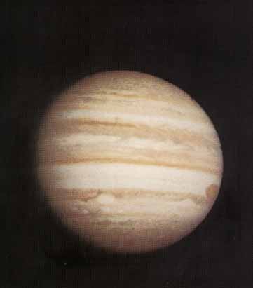
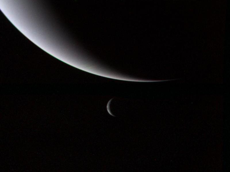
Here are a few images of Neptune taken by Voyager 2
*Neptune Full Disk View*

*Crescents of Neptune and Triton*
*Neptune Clouds*

You can see more pictures taken by Voyager at the [JPL photojournalist website](https://photojournal.jpl.nasa.gov/targetFamily/Neptune?subselect=Mission%3AVoyager%3ATarget%3ANeptune)
Voyager was the first of a class of NASA spacecrafts that could be reprogrammed. This actually ended up being massively important to the mission. For instance, when voyager launched there was no plan to send back images of planets after Saturn. This was only made possible by software uploaded to Voyager 2 after launch.
The **Deep Space Network (DSN)** is NASA’s international array of giant radio antennas that supports interplanetary spacecraft missions.
The DSN consists of three facilities spaced equidistant from each other (approximately 120 degrees apart in longitude) around the world. These sites are:
- Goldstone, California
- Madrid, Spain
- Canberra, Australia
The strategic placement of these sites permits constant communication with spacecraft as our planet rotates – before a distant spacecraft sinks below the horizon at one DSN site, another site can pick up the signal and carry on communicating.
You can go [here](https://eyes.nasa.gov/dsn/dsn.html) to see, in real time, which antennas are currently in use, which spacecraft is communicating with the DSN, data rates etc.

*Canberra DSN complex*