### Moon as relay
It is possible to use the moon as a natural comm...
### First transatlantic optic fiber cable
It wouldn’t take too l...
### Project Echo
Launched in 1960, the metalized balloon had a dia...
*Sir Arthur Charles Clarke* was a British science fiction writer, f...
**MASER** (acronym for Microwave Amplification by Stimulated Emissi...
### Noise Temperature
The noise in a system can be expressed as an...
For a **passive** satellite the following expression can be used to...
You can listen to Eisenhower’s recorded message [here](https://en.w...
The first of fourteen _DSCS-III_ satellites was launched in 1982, s...
**EIRP** (Effective Isotropic Radiated Power) is the measured radia...
Over time satellite communications have been shifting towards highe...
More than 30 different nuclear powered satellites were launched int...

294 PROCEEDINGS
OF
THE IEEE,
VOL.
65, NO.
3,
MARCH 1977
Satellite Communication-An Overview
of
the
Problems and Programs
WILBUR L. PRITCHARD,
FELLOW,
IEEE
Abrmct-This
paper
introduces
the
subject
of
satellite
communica-
tion
in
its
broadest
aspects,
recounts
its
history
and
discusses
the
principal technical problems It
is
primprily communications-oriented
but
relevant
spacecraft
and
launch
considerations
are
summarized.
Tabular summaries
of
the
world’s
satellite
communication programs
are
given.
I. INTRODUCTION
OMMUNICATION satellites have several important
characteristics. One
is
certainly the availability
of
band-
widths exceeding anything previously available for inter-
continental communications. Although overland transmission
of
highquality TV pictures by microwave radio relays or cable
has been possible for some years, trans-Atlantic TV transmis-
sion took place for the first time only after the
first
active
communication satellite had been put in orbit. Interconti-
nental relaying of TV programs, now commonplace,
is
done
exclusively by satellites.
Another, perhaps the most important
of
all,
is
the unique
ability to cover the globe. In the future, it
is
likely that cables
will
use
much higher carrier frequencies, probably as high as
the optical region
of
the spectrum. If
so,
a multitude
of
TV
channels or their equivalent could be transmitted from one
continent
to
another without satellites. However, a cable still
has
two fixed ends and there must
be
a connection between
every pair of points to be in communication. Satellite systems
offer, in this respect, a flexibility that cannot now be dupli-
cated. Furthermore, this flexibility applies not only to fixed
points on earth, but also to moving terminals, such as ships at
sea, airplanes, and space vehicles.
With communication satellites, then, instant and reliable
contact can be established rapidly between any points on
earth, in addition to, and well beyond, the capabilities
of
avail-
able land lines, microwave line-of-sight relay systems, and
other techniques. Satellites are the elements
of
a communica-
tions revolution analogous to that in transportation resulting
from the airplane.
11.
HISTORY
Although the
origins
of the whole idea
of
satellite communi-
cation
are
obscure, there
is
no question that the synchronous,
or more accurately, geostationary, satellite was first proposed
by Arthur C. Clarke in an article in
Wireless World
entitled,
“Extraterrestrial Relays.” He recognized the potential for
rocket launches based on the German V2 work during the war
and also the conspicuous advantage
of
the geostationary orbit.
Prophetidy, his proposal was for the
use
of
these satellites
for FM voice broadcast rather than for telephone service.
Interestingly enough, Clarke also foresaw the
use
in space
of
Manuscript received April, 1976;revised September 7, 1976.
The author
is
with Satellite Systems Engineering, Inc., Washington,
DC 20014.
electric power generated by panels
of
solar cells. Implementa-
tion
of
his
idea still had to wait for the Space Age (Sputnik-
1957) and solid-state technology.
Thirty-one years have passed since
his
prophecy, and there
are now 22 satellite communication programs with satellites
in
orbit or under active construction. There are another score of
programs with earth stations only using the satellites
of
others.
A word
of
tribute to
his
exceptional vision
is
certainly in
order.
A.
The Early Years
Moon reflections for radar and communication purposes
were repeatedly demonstrated in the late forties and early
fifties. In July 1954, the
first
voice messages were transmitted
by the
US
Navy over the earth-moon path. In 1956, a
US
Navy moon relay service was established between Washington,
DC, and Hawaii. This circuit operated until 1962, offering
reliable longdistance communication limited only by the
“availability”
of
the moon at the transmitting and receiving
sites. Power used was 100 kW, with 26-m diameter antennas
at 430 MHz.
A metallized balloon
of
the correct size, launched by a
rocket and placed in orbit can be used as a scatterer of electro-
magnetic waves generated by an earth transmitter. Part of the
energy can be picked up by receiving stations at any point on
earth from which the balloon
is
visible, thus obtaining a pas-
sive communications satellite system.
Through the joint action
of
Bell Telephone Labs, NASA, and
JPL, the ECHO experiment was performed. Successful
communications across the
US
were first established in early
August 1960, between Goldstone, CA, and Holmdel, NJ, at
frequencies
of
960 MHz and 2290 MHz. The ECHO “balloon,”
in an inclined orbit at 1500-km altitude, was visible to the
unaided human eye.
Later in the same month, the first trans-Atlantic transmis-
sion occurred between Holmdel, NJ, and a French receiving
station [I]. This project alerted the entire world to
be
prospect of the new medium
of
communications although the
specific method was never exploited commercially.
Although passive satellites have infinite capability for
multiple-access communications, they are gravely handicapped
by the inefficient use
of
transmitter power. In the ECHO
experiment, for instance, only one part
in
10l8
of
the trans-
mitted power (10 kW)
is
returned to the receiving antenna.
Since the signal has
to
compete with the noise coming from
various sources, special low-noise receivers must be used.
Luckily, the invention of the maser in 1954 and its successive
development, permitted the construction of very low-noise
receivers (with temperatures in the neighborhood
of
10
K
which, used with horn-reflector receiving antennas having an
aperature
of
about 43 m2, made possible the transmission of
teletype, voice, and pictures).

PRITCHARD: WORLD’S SATELLITE COMMUNICATION
295
The advantage of passive satellites is that they do not require
sophisticated electronic equipment on board. A radio beacon
transmitter might be required for tracking, but in general,
neither elaborate electronics, nor, with spherical satellites,
attitude stabilization is needed. Such simplicity, plus the lack
of space-flyable electronics in the late fifties, made the passive
system attractive in the early years
of
satellite communications.
As soon as space-flyable electronics became available,
it
was
obvious that passive systems would be replaced by active
satellites. The mathematics
of
the inverse
square
law for active
satellites (versus the radar-like inverse fourth-power law appli-
cable to passive satellites) are overwhelmingly in favor
of
the
former.
The relative disadvantages
of
a passive system increase with
orbital altitude and the on-board power availability of the
active satellite. After the early experimental
trials,
all subse-
quent satellite communication experimental and operational
systems have been
of
the active type, and there
is
nothing to
indicate that the situation
is
likely to change.
It is interesting
to
note that the first active
US
communica-
tion satellite was a broadcast satellite. SCORE, launched on
December 18, 1958, transmitted President Eisenhower’s
Christmas message to the world with a power
of
8
W
at a
frequency
of
122 MHz. SCORE was a delayed-repeater
satellite receiving signals from earth stations at 150 MHz; the
message was stored on tape and later retransmitted. The 68
kg payload was placed in rather low orbit (perigee 182 km,
apogee 1048 km).
The communications equipment was battery powered and
not intended to operate for a long time. After 12 days
of
operation, the batteries had fully discharged and transmission
stopped.
B.
The Experimental Years
Aside from early space probes like Sputnik, Explorer, and
Vanguard, as well as the SCORE and Courier projects, which
were early communication satellites of the record and re-
transmit type, the major experimental steps in active com-
munication satellite technology were the Telstar, Relay, and
Syncom projects.
Project Telstar is the best known
of
these probably because
it was the first one capable of relaying TV programs across the
Atlantic. This project was begun by AT&T and developed by
the Bell Laboratories, which had acquired considerable knowl-
edge from the early work
of
John R. Pierce and his associates,
and from the work with the ECHO passive satellite. The first
Telstar was launched from Cape Canaveral on July 10, 1962.
It was a sphere of approximately 87 cm diameter, weighing
80 kg. The launch vehicle was a Thor-Delta rocket which
placed the satellite into an elliptical orbit with an apogee
of
5600 km, giving it a period of 2-$ h.
Telstar
I1
was made more radiation resistant because
of
experience with Telstar
I,
but otherwise,
it
was identical to
its predecessor. It was successfully launched on May 7,1963.
The power of Telstars
I
and
I1
was 2.25
W
provided by a
TWT, with an RF bandwidth of 50 MHz at 6 and
4
GHz. Both
satellites were spin-stabilized. The overall communication
capability was 600 voice telephone channels, or one TV
channel. To overcome the low camer-to-noise ratio avail-
able in the down-link, receivers at the earth stations used
FM
feedback in order
to
obtain an extended threshold. Even
though the Telstar system was superbly engineered, it was
designed as an experiment and was not intended for commer-
cial operation. Among other things, the orbit used made it
only visible for brief periods.
A
project with similar objec-
tives, Project Relay, was developed by the Radio Corporation
of America under contract to NASA. It was similarly
successful.
In early 1962, the President sent proposed legislation to
Congress to start the commercial exploitation
of
these suc-
cesses. After extensive hearings on the Bill, the
US
Congress
passed the Communications Satellite Act of 1962, which led
to the establishment
of
the Communications Satellite Corpora-
tion in 1963.
On August 20, 1964, a significant event occurred when
agreements were signed by 11 sovereign nations which resulted
in the establishment of a unique organization-the Interna-
tional Telecommunications Satellite Consortium, known as
INTELSAT. This new organization was formed for the pur-
pose of designing, developing, constructing, establishing, and
maintaining the operation of the space segment of a global
commercial communications satellite system.
C. The Commercial Era
Commercial communications by satellite began officially in
April 1965, when the world’s first commercial communication
satellite, INTELSAT
I
(known as “Early Bird”), was launched
from Cape Kennedy. It was decommissioned
in
January of
1969 when coverage of both the Atlantic and Pacific was
accomplished by two series of satellites, INTELSAT’s
I1
and
111.
Interestingly enough, Early Bird was planned to operate
for only 18 months. Instead, it lasted four years with 100 per-
cent reliability.
The fully mature phase of satellite communications probably
is
best considered as having begun with the installation of the
INTELSAT IV into the global system starting in 1971. These
spacecraft weigh approximately 730 kg in orbit and provide
not only earth coverage but
also
two “pencil” beams about 4’
in diameter which can be used selectively to give spot coverage
to Europe and North and South America. INTELSAT IV is a
spinning satellite, as were its predecessors, but the entire
antenna assembly, consisting
of
13 different antennas,
is
stabilized to point continually toward the earth. Two large
parabolic dishes form the two spot beams. Each satellite pro-
vides about 6000 voice circuits, or more, depending upon how
the power in the satellite
is
split between the spot beams and
the earth coverage beam. INTELSAT IV can carry 12 color
TV channels at one time.
D.
Military Satellites
The first military satellites, the DSCS-I, were launched by
the
US
Air
Force in June
of
1966. These launches were
interesting because
8
satellites were launched simultaneously.
Finally, about 30 satellites
of
a very simple spinning type and
without station-keeping were placed in near synchronous
orbits. Some are still in operation today. The DSCS-I1 system
was initiated several years ago and constitutes the present
US
military system although it has had both spacecraft and launch
vehicle failures. DSCS-111
is
being planned.
111.
CATEGORIES
OF
SYSTEMS
There are some 42 satellite communication systems in the
world today, 22
of
which include both satellite and terrestrial
equipment (See Table
I).
By satellite system, we mean one
which is in active operation or one for which the equipment
is
being built under funded contract. There are literally dozens

296
PROCEEDINGS
OF
THE
IEEE,
MARCH
1977
TABLE
I
LIST
OF
PROGRAMS
1
-I
Cl...
Statu'
Coveram.
:6
-
x:
RODr-
?r.qwrSy
sada
Date
--
om)
IIRLull
5925
-
6425 up 1965
xx
X
2
US%
3
~I-lrud.
4
Ycston
hln
I
ICIutQLl
xxx
X
X
5725
-
6225
up
3400
-
3900.
ooo
-
lwo
dam
1965
xxx
3700
-
4200
dan
(C
Wd)
X
X
xx
xx
Snre
an
YESTAR
1976
5927
-
6403
3702
-
4178
1973
1974
5925
-
6425
3700
-
4200
6
kEFiXM
&TLLXTg
ccV.*
7
COnutIA~
(-)
YESrAR
Trnnapmder
1974
xx
X
X
X X
5925
-
6425 3700
-
42w)
1976
xx
14152.5
-
14192.5 11490
-
lU30
1977
X
8
i?sA
(on/ocr)
14242.5
-
14362.5
14455.0
-
1U60
1UM)
-
11700
11792.5
-
11797.5
9
ULL)u*
10
llmmzsu
X
xx
IhTEWT
Tranapoder
1975
X
X?
14WO
-
14500 11700
-
12200
liu
had
1978
X X
X
5925
-
64425
3700
-
4200
1976
xx
c
hnd
2500
I'caat
1980-90
x
X
X
c
or
YU
2500 B'cast
11
XalUTnam
su
X X
X
12
ms
u
PnILIPPMLs*.
14
TmLI
xx
1975
INIELSAT
Transponder
X
X
X X
5925
-
6425
3700
-
4200 1976
,lS
uu
-
16
CQ5ATcemU@AUUT)
Satellite
-
Ship
Satellite
-
Sa*
1975
xx
X
300
-
312 1638.5
-
1662.5 up 6174.5
-
6425
up
248
-
260
1537
-
1541
dun
3945.4
-
4199.0
d-
1645
-
1660, 131.425
-
131.975
up
SOW
-
5125
up
1541.5
-
1,43 125.511
-
1S.Yl5
dull
3125
-
5210
do.0
1641.5
-
1644.5 up
1U90
-
10500 up
1540
-
1542.5
dm
11690
-
11700
dm
L
hmd
Corhhd
17
ESAlmaUCaerul-
Satallite
-
Ship Ltellitc
&re
198Ot
X X
X
19
==(mu==)
18
IsAo
Satellite
-
Planc
1979
X
X X
20
mopwl
IRWCASTDE
ma
Satellite
-
Crd
X
Satellit.
-
Ship
S.tellite
-
shore
1977
X
X
X
YU
b0J
m
1985
X
Xu
Band
198Ot
X X
21
FEXRM.
RemaLIc
o?
COIIuIll
U
AIS4
22
sw2mm.e
X
X
X
X
xx
5926
-
6424 up 3700
-
4200
dovn
1975
24
JMAI
-
carPlaruna
xx
Ylde
variety
of
axprianta
in
6
C.
S!
UlR,
ad
VR
&do
1974
X X
5925
-
6425
3100
-
4200
1917
xx
25
JAPAP
-
IQ-
14
OW
1978
xx
xx
zh
CIS
X
7975
-
8162 7250
-
7437
1970
X
x
xx
30
NATO
29
m
7900
-
8400
7250
-
7750
1966
xx
x
xx
28
Dscs
xx
X
27
SnIO
X
X
31
PLLTuK*w
xx
X
X
X
1977
Satallite
-
Ship
&toll1t*
-
She+.
32
LE1
SPRXES
xx
xx
x
.x
33
LKU
MIIW
34
ARRQKINA'
35
AU-LU
X
xx
X
1980'.
c
ib.
S
Ud
36
m4zu
X
?
X
31
MIPL.
?X
x
X
xx
X?
1978
5923
-
6425
3700
-
4200
30
IUS
X?
?X
x
x1
ImEWI
Tr.nopoldcr
39
MUYSIA+
X X
X
40
UXICED
KXm
x
1975
rWnWI
Trarupoder
61
sISTF2l.S
USm
I"KLSI*
xx
X
30
WO
12
OW
1975
7976
-
8005
7257
-
7281
1969
17009
-
17782
1977
l4
Oo0
11
OOO
20
ooo
1U31
-
11862
I
xx
X X
225
-
400
7900.bLoo
1965
wide
-rlety
of
exprLnto
at
IAW
.od
K
sad.
X
X
IHnl5AI
Irarupondor
X?
xx
X??
IrnLSAI
Tr.a.por*lcr
X?
--
--
62
ASW
IUIIOFS
XIX
X
X
X X
IWlZlST
Iranapoadcr
Varioua
X
7
.?-r~h
:t.:lsn.
0n:y
of other systems under study in various phases. They range, in
likelihood
of
implementation, from remote possibilities
to
being on the verge
of
realization.
We can characterize and categorize satellite systems in a
variety of manners, either by their technical characteristics or
by their operational
use.
The latter seems more natural and,
indeed,
is
instructive in the sense that after having categorized
the satellites operationally, we can examine the diversity
of
technical methods used to achieve similar operational results.
The first category of system is certainly international civil
telecommunications,
of
which we have only
2
examples
today: the highly successful INTELSAT and the inchoate
STATSIONAR
of
the Soviet Union.
The second category
.is
that
of
regional and .domestic satel-
lites, principally for civil telecommunications but occasionally
for the distribution of television programs. In this class are:
An&, Westar, Satcom, Comstar, Palapa (Indonesia), and
Molniya. For military communications (either to fixed or
mobile terminals), we have
4
systems: NATO, Skynet, DSCS,
and FLTSATCOM.
There are as yet no operational direct broadcast systems
although there are several experimental ones in that category.
It
is
likely that even operational ones will be joined with tele-
communications services.
And, finally, still in the operational rather than the experi-
mental category, we have those systems planned specifically
for communication with mobile terminals: MAROTS,
MARISAT, and AEROSAT.
The experimental programs cover a wide range
of
purposes,
from experimenting with operational problems and proving
spacecraft technology to acquiring propagation data
in
fre-
quency bands of potential interest, especially above 12 GHz.

PRITCHARD:
WORLD’S
SATELLITE
COMMUNICATION
291
In this category, we have:
ATS-6,
Canadian Technology Satel-
lite, the Japanese Communication Satellite, Japanese Broad.
cast Satellite, OTS, Symphonie, SIRIO, and the Lincoln-
Laboratory Series (LES). The
gross
technical features of these
systems are summarized in Table
11.
IV.
MAIN
TECHNICAL CONSIDERATIONS
In order to discuss the various ways in which the different
systems have chosen to cope with the particular technical
problems, we
must
examine, at least briefly, the technical and
operational problems of satellite communications. These
problems cover virtually the entire spectrum
of
physics and
engineering. It is our intent here to look particularly at those
that are special and even unique to satellite communication.
Clearly, a whole range of problems results from the necessity
to insert the satellite into the desired orbit, normally geo-
stationary, to control it remotely, and to maintain it in good
operating condition. Even if satellite communications were
to
consist of passive reflectors, the later problems alone would be
obviously nor negbble. The wide bandwidths now easily
available in the use of satellites in order to be exploited
properly lead to another group
of
problems; many
of
which,
of
course, are familiar in connection with terrestrial microwave
relay.
Most important of all, we have that category of problem
unique to satellite communication that arises from the neces-
sity and desirability
of
exploiting the geometric availability of
a geostationary satellite to any point over almost a third of the
earth’s surface. Before this convenience can be realized, it
is
necessary to choose a system
of
multiple access. In a very real
sense, we can call this
the
problem of satellite communications.
The problems in the three categories are not independent of
each other. We
will
discuss, at least briefly, the most impor-
tant interrelations among them.
A.
The
Communication Link
The exploitation of the wide bandwidth and the multiple
access problem, and the related question of choosing appro-
priate modulation systems, are
all
best examined by starting
with the elementary equation for the performance
of
a
communication
link.
The carrier power received at the earth station is given by
where
PT
satellite transmitter power
GT
transmitter antenna
gain
(over isotropic)
AR
earth station antenna effective area
=
CRh2 /4n
h
wavelength
R
distance from satellite to earth station
Li
incidental loss.
The noise density
NO
is equal to
kT,
where
k
is
Boltzmann’s
constant and
T,
is
the equivalent system temperatures defined
so
as to include antenna noise and thermal noise generated at
the receiver. Let
us
further define effective isotropic radiated
power (EIRP) as equal to
PT
GT
and a dimensionless spaceloss
equal to
(4nRIh)’.
It
is
routine
to
show
C EIRP
GR
1
No L,Li
T,
k
-
=-
--
dBHz.
Communications engineers usually make these calculations
in dB by taking 10 times the loglo of both sides of
(2).
Care
should be taken since some terms are dimensionless and some
others are-not. (e.g.,
(C/No)
is in dBHz,
Li
will be in dB, and
EIRP in dBw.)
Even more interestingly, the transmitter antenna gain
GT
is
inversely proportional to the solid coverage angles which in
turn depends on the terrestrial area to be covered
A,,,
Equation
(3)
has been written
so
as to hghlight the most
basic aspects of space communication. On the left side of the
equation are the desired parameters
C/No
and the area to be
covered on the earth. On the right side, by using the reference
simple relations, we have succeeded in eliminating all the terms
other than the transmitted power in the satellite, the effective
physical size of the receiving antenna, the dissipative losses,
and the system temperature.
The camer-to-noise density
(C/No)
can
be
written as
(C/N)B
where
B
is the noise bandwidth and
(C/N)
is the desired
carrier-to-noise ratio.
(C/N)
typically has a threshold value,
the achievement of which will permit substantial improve-
ments in demodulated signal-to-noise ratio. It
will
also be a
function of bit-error rate in digital systems and in general,
depends on the modulation used. It has values between
8
and
13
dB for most space communication systems. We now can
writ e
Equations
(3)
and
(4)
are both fundamental to appreciating
the essential problems of space communications. Although
they have been written for a down-link, the same equations
apply to the up-link from earth station to satellite if appropri-
ate parameters are substituted.
Either one or both links may determine the overall perfor-
mance. It
is
usually assumed that the noise from all sources
(including intermodulation to be discussed later) is additive
and it
is
then easy to show that
(KT
=
($1;
+
(y
+
(y
(5)
No
T
No
D
No
I
where the subscripts
U,
D,
I,
and
T
apply to the carrier-to-noise
density ratios as calculated for the up-link, down-link, equiv-
alent intermodulation noise, and total, respectively.
Note that in both
(3)
and
(4)
certain terms do
not
appear,
e.g., satellite altitude, carrier frequency, and earth station
(GIT).
The carrier frequency has an important secondader effect
since clearly the available transmitter power, receiver temper-
atures, etc., does depend on it’s state of the art at this fre-
quency, but the dependence is not a function of the com-
munication performance equation. The commonly used
figures of merit EIRP and
G/T
are not basic and should be
used with caution. EIRP has an implied coverage and
G/T
an
implied carrier frequency and when used as figures of merit,
this must be remembered.
The implications
of
the term
C/No
are fundamental and
account for its frequent use in communications systems
engineering. If one examines Shannon’s expression for the
information capacity
of
a channel and allows the bandwidth

298
PROCEEDINGS OF THE IEEE, MARCH 1977
TABLE
I1
CHARACTERISTICS
SATELLITE
WLSS
-
__
-
SYSTM
LAUNCH
VEHICLE STABILIZATION MULTIPLE ACCFSS
MODtiLATION
AND
EARTH
STATION
ANTENNA
DIAUEI'ER
CAPACITY PER SATELLITE
1.
IWTELSAT
IV
IKTEISAT
w-a
700
KG.
after
apogee
rotor
firing
apogee
=tar
790
KG.
after
firing
S
ATLW-CEWTAUUR FHPideo
FDU/Fn/FDEvL
29.5
M.
for Std.
A
13
M.
for Std.
B
29.5
n.
7500 channels
+
SPADE
+T,
12,000 channels
+
SPADE+
W
I I
~~ ~
(elliptical orbit)
A-2-e and SL-12
Fn
12
n.
25
n.
1
TJ
channel
+
unspecified telephones
Single
curler
Fn
Uulti carrier FM
Single channel/
carrier.
Delta
Mu-
latlon PSK
TDUA
Heavy
bute
-
301.
Northern
10.1
1.
Network
IV
-
10.1
M.
Tele-
oxmmicationr
Resate
n
8.U./
Thin
mute
S.lU./
4.714.
4.711.
12 transponders of
36
Wz
bandwidth
3.
TELESAT
-
Canada
272.2's. DELTA 1914
I
I
SSB/FM/FDU
Single
c
MIltiple
Access
Vidco.
SCPC:
PSK/TDCI/TOW
24 Video channels w/34
9000
channeldtransponder
WP
bandwldth
-
FLMA:FDX/Fn
6
PQVPSK
for voice data, 4 PSK
for digltal data,
m
color
n
for monochrome
or
data
-
TDHA:
POI/PSK for
voice/
Ion.
1-/
7.
COPISAT/ATT-
(CCMSTAR
)
28,ROO
one-way
tek-
ikony
ch-cls
or
'1,000
data
750
K;.
ATLAS--ZMTAtiR
1.
ESA IOTS/ECS)
I
324
KG.
I
DELTA 3914
1-120
HHz
Transponder
1-40
MHz
Transponder
1-5
MHz
hasponder
FH
Vldeo
4-Phase PSK Eulobem
A
131.
TD(u
Eurobea
B
31.
+
Spot
Beam
I
LO.
1mIA
300
KG.
DELTA 2914
FDWFU
Hultiple
carriers
9.m.
per
transponder 7.311.
I I
Voice:
SCPC-Fn
1.221., =bile term-
lnals
PSK
inals
Data: 2-Phsse coherent 12.81.. shore term-
-
16.
XIUSAT GEWEIW
326.6
KG.
on
S
I~ISlrT)
DELTA 2914
station
t
5-80
kHz
c-.
ch.
for
ground-to-air
and
surveillance
15-40
kHz
corm.
ch. for
air-to-ground
2-80
kHz
C-.
ch. for
ground-to-ground
1-400
kHz
or
10
MHz
experimental channels
~~
.7. ESYtOnsAT GENEIUL
470
KG.
IMROSAT)
B
1
DELTA 3914
.8.
ESA
1-S)
DELTA 3914
466
KG.
B
Voice:
NBFM, PDU and/or
VSDM
La
gain airborne
antennas
-
Data:
PSWFSK
FLM
m
F@nA
TDW
Atnut
lu.
Shore-to-ship: tip to
50
voicehigh-speed data
Ship-to-shore: Up to
60
channels
volcehigh-speed
data
channels
Shore-to-shore: tip to
3
voicehigh-speed
data channels
to
approach infinity as a limit,
it
turns out that the inforrna-
tion that can be transmitted in a channel is proportional
to
If the
RF
power budget,
as
determined from the above
questions, yields a particular
C/No
and if a particular band-
width
B
is
available from a frequency allocation point
of
view,
then
C/(Vo
is
quite
simply divided by the bandwidth to
determine the carrier-to-noise ratio
(C/N)
available for detect-
ability with the particular modulation system. For a fixed
(C/N)
and modulation system,
B
is
proportional to the number
C/NO
f
of
channels.
Thus
the number
of
channels
in
a given coverage
can depend only on the transmitter power, receiver antenna
size, and system temperature as before. Multiple-beam
antennas reduce the coverage and hence increase the number
of
channels for a constant
total
power. If the power
is
divided
among the beams proportionally, then
B
remains constant for
each beam and the
total
bandwidth available 'per satellite
increases by the number
of
beams.
Increasing capacity by increasing
B
through frequency reuse
so
as
to avoid the limitations
of
(4)
costs considerably in

PRITCHARD: WORLD'S SATELLITE COMMUNICATION
TABLE
I1
(con?)
299
22.
SYMPHONIE
'
230+5KG.
B
I
DELTA
2914
!
i
1
23.
as-6
1356
KG.
B
TITAN 111-C
'I
!I.
8M.
M.
1200
one-way
telephaly
~
2
color
TV
channels
or
I
,.9H.
I.
IVariousI
12
Video channels
at
2.6
GHz
11
Video channel at UHF
(860
MHz
I
C-band transponder has
40
NHz
I
bandwidth
11.5
GHz
transponder has
or
12
MHz
bandwidth
I
-
0.911.
1
lV
Channel
I
-
2.43M.
-
3.0%.
11
sound broadcast
channel
-
9.14M.
I10
duplex
vmce
channels
:X,
Video
!
I
26.
CTS
350
KG.
B
I
DELTA
2914
27.
SIR10
188
KG.
THOR-DELTA
t.
,.
.M
Video
>M
Sound
LO
ch.
(FDMI
of
broadcast
FM
duplex
YOLC~
t
CY-PSK,
2-phase
far
voice
Inarrow
band
'H
or
Dmital
for
lv
comunlcations)
cations)
(videband cmuni-
12
-
100
kHz
telephone channel:
total
1.5
MHz
band-
width
or
1
-
4
MHz
baseband for
TJ
I
500
KG.
S
1
TITAN 111-C
jtaqe
la
Of
proqram:
FDMA
6
cma
<t*'.b
of
program:
FDKA
6
CEHA
stage
IC
Of program:
FDNA
&
CDKA,
phasing
into
TDWPM
rn
itage
2
Of program:
temnals (Fixed1
or
transportable
Total
of
410
MHz
of
232
KG.
S
1
DELTA
2313
(SKYNET
2A
6
281
I
-
'.EM.
12.2M.
11
-
2
MHz
channel
11
;l
-
20
MHz
channel
j24
12400
bps1 data channelS
Iff
4M.
6.4M.
/280
mice
channels
IV
or
1
t;
340
KG.
S
j
DELTA
2914
30. NArO
+
!
'lo
UHF
domlin*
9
UHF and
1
SHE
upllnL
Each
UHF
has
25
kHz
bandwidth
+
IPSK
dovnllnk
2PSK
conferenclnq
link
3-ary
FSK
forward
upllnk
3-ary
MFSK, happed at
200;5ec.
2M.
for
ABNCP
temlnal
IL~~~~~~
jms,
DPSK, to other
!36-38
GHz:
Labs1
!
04.
for airborne
I
20
kb/s,
DPSK.
to
ABNCP
!
LES
satellites
450
KG.
TITAN 111-C
32.
LE5
SERIES
II
,
M.
for
Navy
t&m-
tenn.31,
AN/asc-22
inal
8
ary
FSK
forward
upllnk;
QPSK
conferenclnq
lplink
50
K-ary
symbolshec
from
ABNCf
terminal
75
b/s to
Navy
(s5ipboardl
terminal
ternma1
spacecraft antenna size and complexity. A channel may be
available only in a particular beam and must be switched
if
it
is
desired in another. The switching can be done slowly,
mechanically, as
is
now done in INTELSAT IV and
will
be
done in INTELSAT V. Increased capacity is obtained at the
expense
of
increased transponder complexity-there
will
be
hundreds of switches in INTELSAT V-and a
loss
of flexibility
that is acceptable because
of
the traffic patterns for a world-
wide fixed system. The switching can also be electronic and
rapid, such as would
be
the case in a timedivision switched
satellite in which multiple access was achieved by burst trans-
missions from each earth station that would be switched in the
satellite to the appropriate beam.
The multiple-beam configuration
is
suitable to high-traffic
fixed systems, such as INTELSAT and large-area regional
systems. It is less appropriate
in
domestic systems, such as
Canada, Indonesia, and the United States.
When very high carrier frequencies are used because
of
increased crowding in the more desirable bands, the dissipative
and scattering losses and lower available powers will probably

300
PROCEEDINGS
OF
THE IEEE, MARCH
1977
force multiple-tteam operation even where
it
might otherwise
be undesirable.
Broadcast satellites, especially those for areas covering
several time zones,
will
use
them since the same programs do
not necessarily have
to
go simultaneously to different areas.
The European Broadcasting Union plans, when brought to
fruition, envision multiple beams for Europe.
Satellite connections require up-links and down-links.
Normally, since
it
is relatively easy
to
supply high transmitter
powers and antenna gains at earth stations, the performance
is
determined by the down-link. The limitations
of
satellite
power and the necessity for covering the appropriate terrestrial
area
limit
the overall performance. The problem
is
compli-
cated by the necessity for multiple access and the resulting
possibilities for intermodulation noise in nonlinear tran-
sponders. In the case
of
small terminals, such as in mobile and
data gathering systems, the limitation
is
often in the up-link.
As
we see from
(3),
the ultimate limit in the down-link
performance
is
the transmitted power in the satellite, and this
limitation cannot be avoided for an assigned bandwidth and
the requirement for terrestrial coverage.
Satellite power
is
directly translatable into weight in the
spacecraft and, even more pointedly, into cost. Although the
carrier frequency
is
not a first-order problem in satellite
system planning,
it
has many very important second-order
effects. External sources
of
noise, such
as
the galaxy and
propagation through the ionosphere and atmosphere, are
generally frequency dependent.
B.
Multiple Access
To exploit the unique geometric properties
of
wide-area
visibility and multiple connectivity that go with satellites, the
various communications links using it must be separated from
each other. This can be accomplished in several ways.
I)
Space-Division Multiple Access (SDMA):
One
is
to use
different antenna beams and separate amplifiers within the
satellite. This
is
SDMA. Flexibility
is
only possible at the
expense of complications within the satellite, increased weight,
and occasional operational difficulties.
2)
Frequency-Division Multiple Access (FDMA):
A second
basic way, and the one in most common use,
is
that
of
using
different carrier frequencies for each transmitting station.
This
is
FDMA and permits many stations to use the same
transponder amplifier until finally the overall noise level limits
the capacity
of
that amplifler. Multiple carriers in any non-
linear amplifier produce intermodulation products which raises
the apparent noise level. This requires a "back-off"
of
drive
on the amplifier in order to reduce this intermodulation noise.
The carrier level received
is
less and thus the effect
of
thermal
noise generated in the earth station receiver
is
increased. This
reduction in drive must thus be optimized. Even optimized,
the effect
is
not trivial and the reduction in capability
of
a
transponder over that it would have if all the available infor-
mation was multiplexed on a single carrier frequency can be
as much as
6
dB. Nevertheless, FDMA is the most popular
technique for commercial communication satellites. It
is
efficient
if
one is not power limited, and it
is
the natural
expansion of terrestrial communication methods.
FDMA can be implemented
in
two ways. One
is
to
multi-
plex,
in
the conventional terrestrial manner, many channels
on each carrier that
is
transmitted through the satellite.
Another
is
to use a separate carrier frequency for each tele-
phone or baseband channel within the satellite. If many
carriers are used, the intermodulation problem
is
still more
serious. On the other hand,
it
does approach, asymptotically,
a limiting level that
is
usually acceptable. This single-channel-
per-carrier approach has particular advantages
.in
systems
where there are many
links
to
be made, each one having only a
few circuits
to
be handled at any one time. Normal multi-
plexing
is
very convenient terrestrially but may be economical
only
if
each carrier has traffic, for example, in a group
of
12
channels or more.
Both systems are in extensive
use
today. INTELSAT
uses
both systems, the SPADE system being a singlechannel-per-
carrier multiple-access system. Canada, Indonesia, Algeria,
to
mention a few, use
singlechannel-per-carrier
systems. The
modulation for
singlechannel-per-carrier
systems
is
a separate
decision and in
use
today, we have PCM, Delta modulation,
and narrow-band
FM.
The arguments as
to
which is best are
rather complicated and are discussed elsewhere
in
this issue.
3)
Time-Division Multiple Access (TDMA):
The next basic
method
is
TDMA,
in
w-
'
:h each earth station
is
assigned a
time
slot
for its transmismon, and
all
the earth stations
use
the
same carrier frequency within a particular transponder. In
terms
of
total satellite performance, this
is
the superior
method because the intermodulation noise
is
eliminated and
there
is
an increase
in
capacity. The required back-off
is
much
less,
just
that required
to
achieve acceptable spectrum
spreading.
The
price paid is a considerable increase in com-
plexity
of
the ground equipment. It does seem as
if
the long-
term trend
will
be toward more and more TDMA since
it
fits
naturally with the digital communications systems that are
so
rapidly proliferating terrestrially, not only for data transmis-
sion but more and more for digitized voice.
Various experimental TDMA systems in the
6
Mbit/s
to 60
Mbit/s range have been built and tested by INTELSAT and
others. Their efficiency advantage over FDMA can be
illus-
trated by comparing the approximate channel capacities
of
an INTELSAT IV global beam transponder operating with
standard INTELSAT
30
m earth stations, using TDMA and
FDMA, respectively. Assuming
10
accesses, the typical
capacity using FM/FDMA
is
about
450
one-way voice channels
[
21.
With TDMA,
using
standard
64
kb/s voice frequency
PCM encoding, the capacity
of
the same transponder
is
approximately
900
channels. If Digital Speech Interpolation
(DSI)
is
used to process the PCM bit streams, the capacity is
further increased to about 1800 channels.
A TDMA system went into commercial operation on Telesat,
Canada's system, starting in May 1976. Numerous other
TDMA systems
are
planned for regional and domestic satellite
systems throughout the world.
This trend
to
digital systems both terrestrially and via satel-
lite is reinforced by the ease with which the TDMA methods
can
be combined with SDMA by switching transmission bursts
from one antenna beam
to
another depending on their ulti-
mate destination. This notion
of
time-division switching,
although not yet exploited
in
any satellite, seems inevitable for
the reasons stated in connection with the discussion
on
the
link equation. It
is
efficient in its exploitation
of
both the
satellite power and the frequency spectrum, and both these
resources are in short supply. The price paid
is
increasing com-
plexity. That seems less and less
of
a price considering the
awesome technology
of
large-scale integration and micro-
computers.
Timedivision switching will be a major factor
in
communi-
cation satellite technology.
A
satelliteswitched TDMA system
(SS-TDMA) using a microwave switch matrix
of
redundant
design shows an increase
of
over
30
percent in available

30
1
rApacit~ :over FDMA/TDMA [3] (separate frequency bands,
each carrying TDMA). The satellite-switched TDMA concept
uses a single
400
MHz channel, as distinguished from the
FDMAITDMA system, which
uses
5
channels
of
80
MHz. Its
keying rate
is
300 MBd/s, rather than
60
MBd/s. Four-phase
PSK
is
used, as with FDMA/TDMA. A total channel capacity
of 39
700
is
achieved by SS-TDMA, compared with 29
870
for
TDMADDMA. Note that this time-division switching must be
done in nanoseconds
so
as
to connect successive bursts
to
different spot beams. Diodes
of
the p-i-n type and similar
solid-state switches
will
be necessary and are under develop-
ment along with extensive ancillary logic circuitry.
4)
Code-Division Multiple Access (CDMA):
The final basic
method of multiple access
is
that of CDMA, called occasion-
ally “spread-spectrum multiple access.” In either case, the
idea
is
the same. The transmission from each earth station
is
combined with a pseudo-random code
so
as to cause the
transmission to occupy the entire bandwidth of the tran-
sponder. The station for whom the transmission
is
intended
has a duplicate
of
this pseudo-random code and by cross-
correlating techniques
can
extract it from the “noise level”
created by the simultaneous
use
of
many other stations.
It has considerable advantage in military systems because the
spread-spectrum technique must be used anyway to harden the
satellite receiver against possible jamming and the pseudo-
random sequences are necessary to provide cryptographic
security.
The use of such crypto and anti-jam systems provides
automatic multiple access. In a sense, it
is
free. The difficulty
is
that it
is
not nearly
so
efficient an exploitation
of
the
resources of power and frequency spectrum as is even the
FDMA system, not
to
mention TDMA. In addition, it requires
extra equipment at both ends
of
the link.
Nevertheless, it is used and will continue to
be
used for
military systems. The possibility of its limited
use
in commer-
cial systems may appear as satellite
users
become increasingly
concerned with the possibilities of both malicious interference
and unauthorized listening. Users
of
satellite systems for
commercial data transmission
of
the kind envisioned in
domestic US systems may well be the
first
to consider at least
the crypto secure aspects of these methods.
C. Multiplexing
Multiplexing is the process
of
combining a number
of
infor-
mation-bearing
signals
into a single transmission band. This is
either a terrestrial or satellite problem and is not to be con-
fused with the related multiple-access question. Theoretically
almost any sequence of terrestrial modulation-terrestrial
multiplexing, carrier modulation to the satellite, multiple-
access system-can be used. For instance, the standard
INTELSAT, Telesat, DSCS-1, and Molniya systems use
single-sideband AM and frequencydivision multiplexing on the
ground, FM to the satellite, and separate carrier frequencies
for each earth station. In abbreviation, this system
is
SSB/
FDM/FM/FDMA. The proposed TDMA referred to earlier
would be described as PCM/TDM/QPSK/TDMA. The SPADE
singlechannel-per-carrier system
is
written
as
PCM/QPSK/
FDMA. The most common terrestrial multiplex method in
use
is
frequencydivision multiple (FDM), which
is
used
throughout the world. Frequency-division systems include:
a) single-sideband suppressed carrier (SSC or
SSB);
b) single-sideband transmitted camer (SSTC);
c) double-sideband suppressed carrier (DSSC);
d) double-sideband transmitted carrier (DSTC).
Most terrestrial and space systems use SSB, although some
short-to-medium-haul systems
use
other techniques.
Timedivision multiplexing (TDM) is becoming
of
increasing
interest in satellite communications. Timedivision systems
can use many modulation systems, such
as
pulse-amplitude
modulation (PAM) and pulse-duration modulation (PDM). By
far the most important for satellite communication are pulse-
code modulation (PCM) and delta modulation (DM). Within
these headings there are variations, such as differential PCM
and variable-slope delta modulation. The tradeoffs are
complex.
Although FDM goes naturally with FDMA, and TDM with
TDMA, nevertheless hybrid systems are entirely conceivable
and
will
be used; e.g., a FDM-Master Group Codec (coder-
decoder) has recently been designed for use in the Telesat
TDMA system
[
41
.
A low-loss multiplexer for satellite earth terminals has been
developed to eliminate the broadband high-power transmitter
and thereby improve satellite earth station reliability and
efficiency
[5].
The 5925- to 6425-MHz frequency band is
divided into 12 contiguous channels, each 36 MHz wide. Each
channel
is
amplified with a separate air-cooled TWTA.
Channels can be added by using modular units consisting
of
two 3-dB quadrature filters. Time delay and amplitude
responses are connected with waveguide equalizers placed
before the TWT, thereby avoiding the equalizer loss in the
high-power TWT output.
These units are expected to find wide application in small,
unmanned earth terminals. Successful implementation of
multiplexer and equalization circuits has demonstrated the
practicality of the modular transmitter as an alternative to
single, large, high-power transmitters currently used in satellite
earth stations.
D. Demand Assignment (DA)
Earth stations having continuous traffic over a given number
of
channels
use
preassigned channels. However, many channel
requirements, as in any communications plant, are of a short-
term nature,
so
a channel and terminal equipment economy
technique known as demand assignment is used.
Increased space segment efficiency in a fully variable DA
network arises from the fact that all channels are pooled and
may be used by any station, according to its instantaneous
traffic load. This may be contrasted with a system
using
pre-
assignment in which all channels are dedicated, i.e., both ends
of
the channel are fixed. With this system, when traffic to a
particular destination
is
light, the utilization
is
poor. Also, for
a given system traffic load, the blocking probability for a
system employing preassignment
is
higher than for a system
employing DA. This occurs because some number of channels
are “locked
in”
to a particular link. In a system employing
DA, unused channels may be made available to other users.
Conversely, for a given blocking probability, the number of
channels required
to
pass a given amount of traffic in a pre-
assigned system is greater than in a DA system. The hghter the
traffic per destination, the greater the advantage of the DA
system.
DA offers two main advantages when compared to pre-
assigned systems: 1) more efficient utilization
of
the space
segment;
2)
more efficient utilization of terrestrial intercon-
nect facilities. Corollary advantages are more direct service

302
(the need for “via” or transit routing is eliminated) and a mitted. By making the prediction threshold adaptive, the
consequent possible slight increase
in
communications quality system
can
be made able to respond to rapid changes in traffic
on such
links
because of the elimination of tandem loading.
connections. In application, both SPEC and digital TASI (the digital
There
are
many possible forms which a DA communications counterpart of the well-known Bell system for intersyllabic
system may take, and there are various ways of categorizing channel sharing developed for trans-Atlantic cable
use)
exhibit
their makeup. If, for example, both ends of all channels in the approximately the same advantage but SPEC is superior in its
system are undedicated
so
that any station may
use
any freedom from speech clipping, simple algorithms, lower com-
channel, then the system
is
termed “fully variable.” On the plexity, and lower cost.
other hand,
if
blocks of channels are reserved to an originating Using this approach, a 2:l reduction may
be
achieved in the
station or a destination station, but are
still
used only on bit rate required to transmit a group of voice channels. It
is
demand, then
it
is
a “semi variable” system. important to note that such economies may be achieved only
Another way of categorizing DA systems
is
as follows: when when at least
30
voice channels are processed as a group. One
carriers
(in
FDMA systems) or bursts (in TDMA systems) are
of
the advantages of SPEC
is
its graceful and sut degradation
assigned on demand, the approach may be termed DA multiple in the face of an overload condition.
access (DAMA); when channels on existing carriers (FDMA) or
E.
&,-Board processing
time slots in existing bursts (TDMA) are assigned on demand,
Increases
in
circuit
reliability
that
have
accompanied
then the approach may
be
referred to
as
baseband DA (BDA).
advances
in
solid-state
allow
significant
increases
in
Various
Of
these
approaches may
be
created,
the complexity
of
satellite onboard
circuitry;
con~quently,
the choice
On
traffic
and
On
user
designers now can give serious consideration to advantages of
requirements. For example,
if
a network has a multiplicity of
on-board
processing
previously
considered
too
unreliable.
users but only a few large earth stations, then a BDA approach
Although
on-board
processing
is
being
done
effectively
in
may
be
most
If
there
are
a
great many
earth
the
me
of arth-resourcs and weather involved
in
in
a
each
with
low traffic
a
kge+cale data gathering missions, it has not been attempted
variable DAMA approach would seem
best.
In an application
with
commercial communications
satellites
since
their
chief
where priority control of access
is
vital, the greater restriction
purpose
has
been
the
provision
of
a
link
between
points
on
the
enable a certain number
of
channels incoming to each station
television.
or each of several stations to be reserved for priority traffic.
It
is
also
quite possible and perhaps desirable to
mix
ap-
In military satellites, up-link
signals
accompanied by
proaches within the same system. The choice depends solely
unwanted interference can be converted to baseband, pro-
on the user’s requirements.
cessed for interference removal, and then remodulated on a
down-link carrier. This at least prevents the repeating of the
an example, are characterized by a per-user access technique.
In the SPADE system, for example, each user accesses the
signal in the transponder. The increased noise level must be
satellite with a singlechannel-per-carrier (SCPC). Other
dealt with by other methods.
possible approaches to DAMA are singlechannel-per-bust
sent
using
TDMA
will
be
sorted
on-board
the
Experiments are now being designed in which packets of
(SCPB) TDMA and CDMA. With these approaches, the carrier
(FDMA or CDMA) or burst (TDMA)
is
not transmitted until
This
is
the
previously
discussed
the-division switching.
On-
satellite and transmitted via one of the several spot beams.
it
is
required. The amval at the ground station via a terrestrial
line of a call request results in the establishment of the carrier
board DA, the “switchboard in the sky,” also
is
expected to
or the burst for the duration of the
call.
As stated earlier,
since
satellites
historically
have
been
power
limited,
while
become important toward the end of the coming decade.
these techniques are attractive in systems in which there are a
earth
stations
tend
to
be
bandwidth
limited,
it
is
conceivable
large number
of
users
whose individual traffic requirements are
small.
that a future system may
be
designed
in
which the uplink
The INTELSAT network uses a common TDM signalling
channels are transmitted using single sideband (amplitude
channel on which all stations
call
each other and keep track of
modulation) to minimize bandwidth, while the down-link
the available channels which
are
seized in
turn
on a firstame-
required
from
the
satellite.
Other
combinations
of
up-link
channels are transmitted using PCM/FM to minimize power
first-served basis. This avoids the politically awkward problem
of central controlled systems and the choice of country in
and down-link modulation and multiple-access systems can
which to locate such control-Canada and Algeria, for domes-
arrangements
would
also
be
accomplished
with
demodulation
also
be
conceived for various optimization plans. Such
tic service only, use central common control and avoid the ex-
pense of increased equipment complexity necessary to avoid it.
and remodulation on board the satellite.
(DSI) or speech-predictive encoding (SPEC). In the SPEC
With the launch of CTS, Sirio, and other satellites in 1976,
type system, each voice channel
is
monitored, and the present
the 14/12 and 18/12
GHz
bands
will
enter active
use
for
sample value for each channel
is
compared with the previous
satellite communication. The Japanese also plan
use
of these
sample valfie for the same channel.
If
the samples differ by an
frequencies
in
their BS and CS satellites. Still higher
fre-
amount which exceeds some threshold, (i.e., the present
quencies are under active consideration, not only because of
sample
is
not predictable from the previous sample) the
spectrum crowding in the lower frequency bands, but because
present sample
is
transmitted.
If
the difference
is
less than or
of the desire for broader bandwidths to accommodate higher
equal to the prediction threshold, the sample
is
not trans-
data rates than are now being sent commercially.
of a semi-variable system may be advantageous, since it would ground
for
the unaltered
of
voice,
data, and
DAMA
systems,
Of
which
the
INTELSAT
SPADE
system
is
interference and the nonlinear effect
of
a
BDA may be implemented
using
digital speech interpolation
F. Higher Frequencies

303
COMSAT Laboratories has used
IMPATT
amplifiers providing
about one watt output at 19 GHz (1 6dB gain, 700-MHz band-
width) and at 28.5 GHz (21-dB gain, 1000-MHz bandwidth)
for the AT&T Domestic Satellite Propagation Experiment
[
61
.
Efforts to obtain a
1
to 2 Gbit/s data-transmission capability
have lead
to
interest in the 60-GHz band for privacy and inter-
ference protection from the high oxygen absorption in the
earth's atmospheric blanket; and in the 94GHz band, which
is
the shortest wavelength atmospheric window beyond the
infrared. Millimeter-wave travelling wave tubes can deliver
kilowatts
of
power in the
50-
to lOOGHz range, but they use
very large solenoids or permanent magnets. For the space
segment, tubes
of
lower power (e.g., 60 W) have been
developed using periodic magnet focusing systems based on
samarium cobalt magnet material.
Work has been done at Hughes
[7,
pp. 4-1-4-61 and the Air
Force
[7,
pp. 4-74-12] at 10.6 pm, at which wavelength
NzHeCOz lasers can be built with good efficiency. The 10.6
pm band
is
also being explored by AIL
[
81.
Work on coherent optical
links
is
being done by TRW [91,
by the Air Force [lo], and by NASA. Commoncarrier relay
represents one possible use for optical links, but circuit reli-
abilities are marginal because of weather conditions. Another
severe problem with optical
links
is the extremely narrow
beamwidth, which would require mutual autotracking from
the satellite and earth stations to keep a beam pointed
properly. Such
links
may eventually be useful as supplements
to saturated long-haul facilities.
Inter-Satellite Relays:
Communications between earth sta-
tions that are not both visible to the same satellite require
either the complexities and time delays
of
doublehop transmis-
sion or a link directly from one satellite to another. Because
most of the paths between geostationary satellites would not
involve transmission through the atmosphere, which would
attenuate them, work on intersatellite relays has concentrated
on the use
of
millimeter waves and optics, because
of
the small
aperture requirements when using such wavelengths.
Wavelengths under consideration for such relays are 5 mm
(60 GHz), which
is
highly attenuated by the oxygen absorp-
tion
of
the earth's atmospheric blanket but otherwise un-
affected, and the optical wavelengths of 10.6 and
0.53
pm.
At 10.6 pm,
highly
efficient NzHeCOz laser sources are avail-
able, while the 0.53-pm wavelength takes advantage
of
the
simple detection properties of photomultipliers and the
availability
of
energy from doubled Nd: YAG lasers.
A major difficulty for intersatellite laser
links
is
the acquisi-
tion and tracking of the two widely separated space packages.
Laboratory tests [7] by the
Air
Force have achieved pointing
errors less than 1.2 pm rad peak-to-peak.
Apertures in the 1- to 2-m range and beamwidths of tenths
of degrees are achieved in the millimeter (e.g., 60-GHz)
systems, while apertures on the order of 25 cm are used for
the optical systems. This 1O:l difference, despite a 104:1
wavelength difference, results from the facts that: 1) the noise
levels at millimeter wavelengths are lower by more than two
orders
of
magnitude: and 2) higher efficiency power genera-
tion can be used for millimeter waves at a level at least an
order-of-magnitude higher than for lasers.
The principal issue with respect to millimeter-wave systems
concerns their relative weight. Systems weighing on the order
of 100 kg, drawing
300
W
of prime power and having 2-m
apertures, appear to be feasible.
Weights
of
laser transceivers are projected at less than 90 kg
as a result of the relatively small apertures and higher laser
efficiency which can be used effectively at this wavelength
(10.6 pm).
The chief areas for research and development for intersatel-
lite links, in addition to beam stabilization and system weight,
are
:
a) at
0.53
pm, electrically powered transmitter efficiency
b) at
10.6
pm, the internal laser modulator and its driver
c) at 60 GHz, the reduction of receiver noise through pas-
and reliability;
electronics;
sive cooling techniques.
The
first
test of an intersatellite relay will take place using
LES-8 and LES-9 in the 36- to 38-GHz band.
G.
Antennas
At geostationary altitude, the earth subtends an angle
of
approximately 18".
This,
plus the limited power available on
board satellites, makes the concentration of
RF
output into
narrow beams (e.g.,Q 18") important. However, beamwidth
is
inversely proportional to antenna diameter, which
is
con-
strained by the space available within the fairing
of
the launch
vehicle. Furthermore, attempts to obtain very small beam-
widths (e.g.,
Q
1') may be thwarted by spacecraft attitude-
control precision limitations (it
is
difficult and costly to point
antennas to a high degree
of
accuracy) or by antenna reflector
imperfections. One way of alleviating the problem of fairing
size
is
by the use
of
an antenna that can be deployed in space,
as was done on ATS-6, where a 9.1-m diameter antenna was
contained in a torus
of
2.0-m outside diameter prior to
deployment.
Multiple antenna beams are increasing in importance because
of the need
to
concentrate energy toward different parts of
the world simultaneously. They are
also
attractive from the
viewpoint of frequency reuse, i.e., transmitting different
message groups on the same frequencies, but beaming the
groups simultaneously in different directions toward different
parts of the earth. A single antenna reflector can provide
multiple beams by the
use
of
feeds offset from the focal point.
Separate reflectors, however, provide better efficiency and less
crosstalk.
Omnidirectional antennas serve a useful purpose for telem-
etry and command during the launch and orbital injection
phases of a spacecraft's life, but once the spacecraft's attitude
becomes stabilized correctly, omni-antennas generally serve
only for back-up purposes.
The polarization of
an
antenna's beam
is
govemed by the
polarization of its feeds. (Polarization refers to the orientation
of the electric vector of the radiated field.) Polarization may
be linear or circular. Two linear polarizations (vertical and
horizontal) or two circular polarizations (left-hand and right-
hand) can be used to achieve isolation of transmitted and
received beams from one another, or for the transmission of
two separate message groups in a given frequency band.
I)
Polarization:
Tests on frequency reuse via orthogonal
polarization have been sufficiently successful that the COM-
STAR satellites launched starting in 1976 have dual linear
polarizations with a polarization isolation of
33
dB. The
frequency plan calls for the transponder frequencies on

304
orthogonal polarizations to be interleaved. The RCA Satcom
is
the first satellite to use dual polarization.
Following successful commercial operation of Comstar,
as
well as similar operation planned for INTELSAT IV-A, F-2,
and F-3, it has been predicted
[
121 that the widespread
use
of
dual polarization as a means of obtaining added channel
capacity in the already crowded 6 and
4
GHz
bands. For
example, INTELSAT
V
will
use both the present INTELSAT
polarization and polarization orthogonal to it.
H.
Orbits
To appreciate the various tradeoffs made in the satellite
communications systems, it
is
necessary to look briefly at the
various orbits in which communication satellites
can
be placed,
how they get there, what the ensuing spacecraft problems are,
and how they affect the possibilities for transponder design.
The period
of
an orbiting satellite
is
given by
where
A
is
the semi-major
axis
‘of the eclipse and
p
is
the
gravitational constant 3.99
X
lo5
km3/s2.
For a circular orbit
to have a period equal to that of
the
earth’s
rotation-a
sidereal day 23 h,
56
min,
4.09 s-an altitude of 35803 km
is
required. In the equatorial plane,
this
satellite
will
remain
fiied relative to any point on earth to be “geostationary.”
In
other planes at this altitude, it
will
describe figure eights daily
relative to the earth. The geostationary orbit
is
indeed delight-
ful from many points of view.
An
earth station
can
work with
a
single
satellite, or several with multiple antenna
beams,
with-
out the need for frequent hand-over characteristics of non-
stationary satellites.
Three satellite locations can be configured to permit
covering almost the entire earth. Nevertheless,
it
does have
some disadvantages. It
is
a difficult orbit to get into and it
does not provide coverage of the polar regions. The civilized
parts of the globe are overwhelmingly within the coverage area
of geostationary satellites and the latter limitation
has
not
been
serious
to date. Nevertheless, future marine and aero-
nautical systems may want to communicate to the far
northern and southern latitudes. Certain other application
such
as
data gathering and military communication may also
have the same need. When one considers that orbits meeting
this requirement, such
as
the medium-altitude
polar,
also
permit the injection of much greater payloads into orbit, it
may be that the future
will
see such orbits used for satellite
communication.
Ten years ago there was concern that the combination of
time delay and echo inevitably present on a synchronous alti-
tude
link
with hybrid two-wire to four-wire transformers
would impair intelligibility noticeably. This has simply not
been
a
serious problem except when the required echo
sup
pressors are defective. It
is
no longer a consideration by
system planners
if
voice only
is
used. Data transmission with
long time delay places special requirements on error-correction
protocols. The automatic repeat-request (ARQ) error-
detecting system that requires retransmission must have a
block length chosen to optimize the throughput. This block
length
is
sensitive to both the round-trip delay and the noise-
bitenor rate, normally very low in
a
satellite
link
compared to
terrestrial links. In tandem connections involving the bit-error
rates of
a
mediocre terrestrial
link
with the time delay of a
satellite connection, the overall throughput can be poor. We
may expect that satellite
links
more and more will use forward
error-correction codes that require no retransmission and thus
the time delay again will be of Little significance
[
1 1
]
-
[
151.
Another orbit of interest
is
that of the Soviet Union’s
Molniya used for their domestic communication satellites. It
is
uniquely tailored to the coverage requirements of the far
northern latitudes while avoiding the payload handicaps of a
launch site at these latitudes.
A
highly elliptical 12-h orbit
with apogee over the northern hemisphere
is
used for far
northern coverage.
Normally the major
axis
of any elliptical orbit, called the
line of apsides, rotates slowly because of the nonspherical or
“oblate” earth. There
is
one angle of orbit inclination in
which the effects cancel and
this
angle
is
about 62’. A 12-h
period orbit at this angle and with apogee of the ellipse over
the northern hemisphere
is
reasonably convenient for northern
coverage. It
is
also
an
easy orbit in which to launch payloads
from sites at northern latitudes.
The
geometry of launches
states that any orbit inclination less than the latitude of the
launch site (for instance equatorial) requires a
turn
or “dog
leg.”
The loss in useful payload can
be
quite noticeable for far
northern sites.
This
undoubtedly contributed to the ,%;et
decision to
use
an inclined orbit from launch sites above
45
N
and the French decision to locate its launch facilities at
Kourou, French Guiana-almost
on
the equator. This inclined
orbit system gets northern coverage and
high
payloads in orbit
at the expense of multiple satellites and stringent backing and
“hand-over” problems. It
is
not as convenient
as
a synchro-
nous system for most applications.
I.
Spa
ce
cra
f
t
Several aspects of spacecraft design deserve discussion
since
they affect the communication performance
in
varying ways.
They are attitude control, primary power sources, and pro-
pulsion.
Once a communications satellite
is
on station, its attitude
must be held fixed
so
that its antenna beams are always
directed
as
desired. Effects such
as
gravity gradient (the
difference in gravitational attraction caused by
the
difference
in distance to the
earth’s
center of mass of different parts of
the spacecraft), the earth’s magnetic field,
solar
radiation pres-
sure and uncompensated motion of internal motors, gear
trains, and lever
arms
all constitute disturbing forces acting on
the spacecraft. All but the internal torques are quite small but
continuous, whereas the internal torques, although large, are
of short duration.
The simplest form of stabilization
is
that of
spinning
the
satellite in orbit at a rate of 30 to
100
rpm. This makes the
satellite act
as
a
gyro
wheel
with
a
high
angular momentum.
The satellite’s angular-momentum vector provides attitude
“stiffness.” However, it requires that the antennas be
“despun”, i.e., located on a relatively low-inertia platform
spinning in the opposite direction
so
that the net effect
is
a
stationary antenna beam relative to the earth.
A
bearing and
power transfer assembly then couples the spinning and despun
portions of the spacecraft. Spin stabilization
also
means that
a given solar cell
is
effectively illuminated by the sun only
l/a
of the time, thus causing the primary power to be only l/a of
the value it would have been
if
the cells were not spinning.
Rather than spinning a substantial fraction of the satellite,
angular momentum can be provided by
using
a fly wheel
spinning about the pitch axis and mounted inside. In this case,
the entire satellite
is
the “despun portion.”
This trend in dual-spin designs
is
toward despinning a larger
percentage of the satellite’s mass. This trend
will
continue as

305
multiple beam ant~nnas become more common. Systems such
as INTELSAT
V
and
DSCS-111
will have severe requirements
of
this kind.
The question arises of when the stabilization system
is
no
longer to be classified “dual-spin” but rather “three-axis with
spinning drum providing angular momentum.” One possible
definition
of
dual-spin stabilization
is
that the spinning portion
of
the satellite performs functions other than providing
angular momentum.
As
solar
arrays and antennas become very large (10 m on a
side, or in diameter), the problem of adequately balancing
solar
disturbing torques becomes difficult, and full three-axis
stabilization becomes necessary. More and more satellite
designs are
of
this type.
I)
Attitude Control:
A comparison
of
dual-spin versus
three-axis stabilization
is
instructive. The following three
points explore dual-spin advantages relative to three-axis
stabilization.
a) Simpler attitude-sensing system:
Scanning is provided
by the spinner, arid the spin momentum eliminates the need
for direct measurements
of
yaw angle.
b) Minimum number
of
jet thrusters:
The propulsion
system obtains ullage control (i.e., the feeding
of
propellents
to
the nozzles) from the centrifugal force of the spinner; a
minimum number
of
jet thrusters are required and the same
relatively high
thrust
level can be used for station keeping as
well as attitude control.
c) Attitude “Stiffness:”
The spinning momentum creates
attitude stiffness that reduces the effects
of
torques which are
created within the spacecraft and
also
prevents a rapid accu-
mulation
of
attitude error
as
a result
of
environmental torques.
Ground command thus has enough time
to
provide compen-
sation.
This
attitude “stiffness”
also
can
be used for attitude
control during
an
apogee motor burn (this
also
applies
to
a
three-axis system, but
to
a lesser degree).
The
following four points explore disadvantages of dual-spin
relative
to
three-axis stabilization.
d) Vulnerabih’fy:
A
single catastrophic bearing-failure
mode
can
cause a total telecommunications outage with dual-
spin stabilization. Vulnerable
sliprings
and brushes, and
binding of the despin bearings can cut
off
communications,
thus rendering the satellite useless. Furthermore, power losses
associated with transferring RF
sjgnals
increase with fre-
quency, and redundant encoders/decoders may have
to
be
used on both sides
of
the mechanical despin mechanism.
e) Spacecraft diameter limitations:
A
spinning body, to be
stabilized about a, desired axis, should have a higher stable
shape than a pencil, for example. If the spacecraft diameter
is
limited by the launch vehicle fairing, then this constraint
is
very serious.
f)
Nutational Instability:
Mechanical damping is needed
on the despun platform
to
compensate for nutational instabil-
ity (i.e., “coning”) that results from an unfavorable ratio
of
spin-to-lateral moments of inertia and by energy dissipation
from fuel ‘sloshing
in
the tanks in the spinning portion of the
spacecraft.
g)
Power:
More solar cells are needed for a given power
when mounted on a rotating drum, resulting in a weight and
cost penalty. This factor
is
increasing in importance because
of
the need for more RF power output from any single
antenna, the need for more channels, the use
of
higher fre-
quencies with their lower efficiency transmitters, and more
onboard data processing and automation.
Some general considerations are: reliability of the three-axis
design
is
decreased by the more complex attitude-sensing
system which it requires, but the sensing system can be made
redundant; and dual-spin reliability
is
degraded by the plat-
form despin system, which cannot easily be made redundant.
Spacecraft costs for the two design approaches appear
to
be comparable.
2)
Primary Power
a)
Solar
Cells:
Primary power for communication satellites
mostly
is
obtained by the
use
of silicon
solar
cells. They may
be fixed to the spacecraft body, or mounted
so
that they
can
be
oriented continuously for maximum
solar
energy.
During the equinox seasons, a geostationary satellite
will
be
eclipsed by the earth.
This
means that the satellite
will
be in
the dark for up
to
70
min
per day, depending on the incli-
nation
of
the orbit and the number
of
days before or after
equinox. To maintain operation during such periods, com-
munication satellites depend upon internal batteries, usually
consisting
of
nickel-cadmium cells, although nickel hydrogen
and other technologies are improving swiftly. The batteries
represent a major tradeoff among weight, power, and
performance.
To avoid the
solar-cell
battery limitations, consideration has
been given to the
use
of
nuclear
cells
for powering satellites.
Either radio isotope thermoselectric generations (RTG) or
nuclear reactor powered turbines
can
be used.
A
kg of
UB5
could supply
2.5
MWh
of
energy even at a 10 percent con-
version efficiency. With a half-life
of
lo8
years, it would
outlast most spacecraft.
The advantage of the nuclear supply over
solar
power
systems
is
that no
solar
orientation is required nor
is
any
battery needed. However, heavy shielding
is
required
to
protect the payload from radiation. This disadvantage has
caused solar
cells
to continue to be the preferred primary
power source for communications satellites. Nuclear fuel
handling continues
to
present safety problems both during
manufacture and in the event
of
launch malfunctions. The
safer fuels, such
as
Plutonium, Curium (CmN4), etc., are very
expensive. Strontium (Sr9’), although much cheaper and with
a convenient half-life
of
25
years, is very dangerous to handle.
b) Propulsion:
After launch, one or two types of propul-
sion are required. Satellites launched by Thor-Delta or Atlas-
Centaur launch vehicles inject into transfer orbit only and
require the use
of
an apogee kick motor for injection of the
satellite into geostationary orbit. The weight of this apogee
motor and its propellant
is
typically equal
to
that
of
the
weight of the rest of the spacecraft.
Spacecraft launched by Tital III-C “direct injection” launch
vehicles do not require a separate apogee kick motor, the
functions of orbit circulation and inclination removal being
performed by the launch vehicle itself.
Because of anomalies
in
the earth’s gravitational field and
the perturbing effects
of
the sun and moon,
all
spacecraft
require a small propulsion system for station keeping. Changes
in longitudinal position may be desired from time to time and
also require propulsion.
Hydrazine
is
very popular as a monopropellant because it
has
high
density for storage, low molecular weight and
high
specific impulse. It
is
dense, storable, and catalytic; i.e., it
needs no oxidizer but dissociates on its own.
The change in velocity of a spacecraft
Ar
that can be
achieved (e.g., for station keeping or apogeekick purposes)
is
AV
=
~eln
Mo/Mb
(7)

306
PROCEEDINGS
OF
THE IEEE, MARCH
1977
where
Ve
=
exhaust velocity,
Mo
=
mass of spacecraft plus
hydrazine, and
Mb
=
mass
of
spacecraft (all hydrazine burned).
The exhaust velocity
is
telated to
I,
the specific impulse, by
the expression
v,
=gI
where
g,
the acceleration due
to
gravity (at the earth’s sur-
face),
is
9.8 m/s2.
I,
specific impulse,
is
measured in seconds
and
is
a property of the propellant.
By equating molecular kinetic energy to 1/2 kT per degree
of
freedom
d
la Boltzman,
it
is
seen that velocity
is
propor-
tional
to
the square root
of
the absolute temperature and
inversely proportional to the square root
of
the molecular
weight
of
the propellants; thus, the importance of
high
temperature and low molecular mass
is
readily seen. Equation
(7)
can be used for sizing apogeekick engines and hydrazine
station-keeping systems. Its important attribute is the “loga-
rithm.” This makes the increase in velocity changing ability
of
any propulsion system insensitive
to
increases in propel-
lant weight carried. The efficient way
to
improve the cap-
ability
is
through high specific impulses, that
is,
higher escape
velocities for the propellant molecules. It explains the great
attractiveness for future work
of
ion engines where the
particles are accelerated
to
high velocities electronically.
Specific impulses
of
several thousand seconds are easily
achieved. They are still experimental, but one
can
expect their
use
during the next decade. The correction
of
latitude in
synchronous orbit, because
of
the perturbing effects
of
the
gravity
of
the sun and moon, require a
Au
capability
of
perhaps 100 m/s/yr over a long period-a high value and a
natural for ion engines. Longitudinal corrections because
of
a
noncircular earth are very much smaller-perhaps
5
m/s/yr-
and would probably continue to be made by hydrazine
engines. Even they
will
probably be improved by various
techniques, the most promising of which seems to be heating
the hydrazine thermally.
c)
Engine Type and Propellant:
The choice of engine type
and propellant is another major tradeoff area. Accuracy in
station keeping simplifies the earth station tracking problems,
but at the expenie
of
hundreds
of
kilograms
of
propellant in
spacecraft
of
the INTELSAT class.
Ion engines
[
161, because
of
the
hjgh
exhaust velocity pro-
vided by electronic acceleration, offer hope
of
large reductions
in propellant requirements but their technology
is
still
not
mature enough to be acceptable to operational spacecraft
designers.
J.
Launch
The delivery
of
a communication satellite to its geostation-
ary position takes place in four steps:
a) ascent;
b) parking orbit;
c) transfer orbit;
d) insertion into final orbit.
The spacecraft mass that
can
be placed into geostationary
orbit
is
maximized by injecting the spacecraft into a transfer
orbit at an equatorial crossing.
This
means that the spacecraft
with its second and third states must coast in the parking orbit
until the right time for the injection burn, which uses both the
second and third stages and accelerates the spacecraft to
36
700
km/h.
SPIAC~CR~FT Wlltl APOGEE
PLUS SPACECRArl
MOlOR
OR
LV UPPER STAGE
h
LV UPPER SIAG
INJtClION
BUR
LV UPPER STAGF
OK\
/
APOGt.C M010RORBllAl
-
INSERTION
BURN
(1850mivt
GI
OSIAllONARY
ORBIT
Fig.
1.
Typical profile
of
a geostationary equatorial
mission.
Fig.
1
shows the geometry and events for the transfer orbit
and orbital insertion phases
of
a geostationary mission. It
shows
the transfer-injection burn occurring at the second
equatorial crossing, where the launch vehicle places the space-
craft into a transfer orbit with its apogee equal
to
geosyn-
chronous altitude.
Actually,
to
achieve geostationary orbit, another velocity
impulse
is
required at the apogee
of
the transfer orbit
to
remove the orbital inclination caused by the launch site lati-
tude and
to
make the final orbit circular. This last velocity
increment can be obtained from the launch vehicle upper stage
or from the spacecraft
[
171
.
Current communication satellites
launched from Cape Canaveral insert themselves into
final
orbit by
use
of
a solid propellant moor. The Titan 111-C,
however, has an upper stage called the Transtage which
performs both the transfer orbit and the final orbit injection.
Cape Canaveral in the
US
is
used for launches in which
use
of
the rotation
of
the earth
is
desired in order
to
increase the
velocity
of
the vehicle, i.e., for eastward launches. Most
communications satellite launches take place here. The
Western Test Range
(WTR)
is
used mainly for southernly
launches into near-polar orbits.
The latitude of Cape Canaveral (nearly 29’N) places it at a
disadvantage for launches into geostationary equatorial orbit
compared with sites closer
to
the equator. Accordingly, the
European Space Agency (ESA) is building an Ariane launch
facility at its Kourou, French Guiana, launch site, which
is
at
approximately 5’N latitude. Other nearequatorial sites are at
Sriharikota and Thumba (Trivandrum) India and San Marco,
an Italian mobile platform base off the coast of Kenya.
Launch vehicles available for satellite communication,
especially
to
geostationary orbit,
fall
in several groups. The
most important to date
is
that group putting spacecraft into
synchronous transfer or low orbit only, e.g., the Thor-Delta
in
its many versions, AtlasCentaur, and the Titan-Agena. The
Titan 111-C brings the spacecraft directly to synchronous orbit,
without requiring the
use
of
an apogee-kick motor. This
is
a
very convenient method for the spacecraft designer since he
does not have
to
design for the apogee kick and transfer orbit,
but
it
is expensive.
On the horizon
is
a new vehicle being developed
in
France,
the Ariane, which
will
be in the first class but with payload
capability almost equal
to
Atlas Centaur. It will
go
from
Kourou with all the advantages of an equatorial launch site.
Even more interesting will be the NASA shuttle. It will
permit very large and complicated satellites to be placed in

PK€TiTLATD3iTjRL~S SATELLITE COMMUNICATION
200
km parking orbits, but it will be necessary to transfer
them to the ultimate operational orbit, normally geostation-
ary. Ultimately an auxiliary vehicle called the “tug”
will
be
developed to do this transfer in a recoverable fashion.
Without the tug vehicle to do this, it will be necessary to
provide both perigee and apogee stages on the satellite itself,
and this will permit launching about one-quarter of the
parking-orbit weight into the geostationary orbit.
The economic and operational tradeoffs
are
extraordinarily
complicated. At this moment, it does, indeed, seem as
if
this
may be an efficient and economic way of launching geosta-
tionary payloads although the final decision will depend on
the total number of shuttle launches. It seems quite possible
to design restartable liquid engines, or a combination of liquids
and solids, that will transfer. the satellites from parking to
geostationary orbit efficiently.
Besides the ability to check a spacecraft before putting
it
into synchronous transfer and after it
has
experienced the
worst
in launch environment, the shuttle
will
have another
feature of particular interest to communication satellite
designers. It
will
permit the
use
not only of much heavier
spacecraft but
also
a bigger spacecraft physically. Notably the
diameter of spacecraft can go up to about
5
m. Current
spinning satellite designs are seriously hindered by the limit of
about
3
m on the diameter which forces large, highcapacity
spacecraft to be long and slender. As mentioned previously,
this makes them inherently unstable dynamically, and requires
sophisticated damping
in
order to prevent catastrophic
nutation.
An increase in diameter from
3
m to
5
m
will
increase the
desired moment of inertia by almost
3
times and make the
spacecraft a good deal more stable. In addition, recent
developments of solar-cell technology also favor the continued
use of spinning satellites because it again permits more primary
power for a particular diameter.
V.
CONCLUSIONS
In a sense this paper, as a survey of the satellite communica-
tion field,
is
its
own
conclusion. One need only glance at
Table
I,
a list of the world’s programs in all categories, to
realize that as an industry, satellite communication has arrived.
Table
I1
lists more detail on those programs that include
satellites. A complete listing of the characteristics of all those
systems would occupy hundreds of pages
[
121 but we have
tried to excerpt those characteristics that epitomize each
system. The aggregate serves to make one appreciate the
variety of programs already
in
existence and to make predic-
tions of the future safe, in the sense that the magnitudes
will
clearly increase and risky in the sense that there are
so
many
diverse possibilities.
With 94 nations participating and some
80
percent of the
world’s overseas traffic going by satellite, INTELSAT’s role
is
clear. Yet this
is
only a small part-domestic traffic and ser-
vices to mobile platforms will probably represent the greatest
part of satellite traffic ten years from now. The satellites will
continue to exploit the solid-state revolution
so
as to permit
increasingly complicated spacecraft and communications
services. One can expect on board message switching and pro-
cessing in great quantities. The military organizations of the
US and other countries and groups
will
expand their satellite
307
activities
so
as to exploit the spectacular tactical possibilities.
Digital technology will predominate in future development, but
FM and FDMA will be around for a long time. Broadcast
satellites, long possible technically but involved institutionally
and sensitive politically,
will
slowly come into their
own.
Antenna techniques to restrict useful signal levels to within
a national boundary will be developed. The ability of NASA’s
shuttle to launch large payloads-and of continuous rather
than quantized sizes-will make the exploitation of
all
the
techniques easier.
R&D programs of
all
kinds will continue-in orbit and on
the ground
so
as to foster the continued development of a
mature technologically oriented industry.
Any kind of extrapolation
of
the past ten years leads to a
predicted activity for the next ten that
is
staggering.
ACKNOWLEDGMENT
The author
is
grateful to Horizon House-Microwave, Inc., of
Dedham, MA, for permission to quote freely from their study
entitled “Communications Satellite Systems Worldwide, 1975-
1985.” Much of the tabular material and some text has been
extracted from this study.
REFERENCES
(11
BellSyst. Tech.
J.,
July 1961.
[2] D.
G.
Gabbard and P.
Kaul,
“Time-division multiple access,’’
in
Eascon Rec.,
pp. 179-188,1974.
[3] T. Muratami, “Satelliteswitched time-domain multiple access,”
inEascon Rec.,
pp. 189-196,1974.
[4] H. Kaneko,
Y.
Katagiri, and T. Okada, “The design of a
PCM
MasterGroup Codec for the Telesat TDMA system,” in
Conf.
Rec., Int. Conf. Communications,
vol.
3,
pp. 44-6 and 44-10,
June 1975.
[SI
R. W. Gruner and E. A. Williams,
“A
low-loss
multipkxez for
satellite earth terminals,”
COMSAT Tech. Rev.,
vol. 5, no. 1,pp.
[6] R. Sicotte and
M.
Barett, “Centimeter-wave
IMPATT
amplifiers
[7]
J.
D. Barry,
et ul.,
“1000 megabits per second intersatellite
laser
for space communications,”in
Eascon Record,
p. 412,1974.
communications system technology,”
in
Con$ Rec., Inter. Conf.
Communications,
vol. 1, pp. 4-1-4-6,4-7-4-12, June 1975.
[SI
B. J. Peyton and A.
J.
D. Nardo, “Systems measurements of a
CO,
laser
communications
link,”
in
Conf. Rec., Int. Conf. Com-
munications,
vol. 3, pp. 4-13-4-17, June 1975.
[9]
N.
Killen,
‘‘Digital communications performance
using
both
temporal and spatial modulation,”
in
Conf. Rec., Int. Conf. Com-
munications,
vol.
3, pp. 4-18-4-22, June 1975.
[lo]
W.
L.
O’Hern,
Jr.,
“Applications of optical communications
in
space,” in
Conf. Rec. Int. Conf. Communications,
vol. 3, pp.
157-177,
Spring
1975.
I
I
428-4-32, June 1975.
111
Heller and Jacobs, “Viterbi Decoding for satellite and space
communications,”
IEEE Trans. Commun. Technol.,
vol. COM-19,
12
1
W.
L. Pritchard
et al., Communications Satellite Systems World-
wide,
1975-1
985. Dedham, MA: HorizonHouse Microwave,
1975.
131 Cacciamani and Kim, “Circumventing the problem of propaga-
tion delay
on
satellite data channels,” in
Data Communications
141
Cohen and Germano, “Gauging the effect of,Fropagation delay
and error rate
on
data transmission systems,
Telecomrnun.
J.,
~~
pp. 835-848, Oct. 1971.
M1.
37,
PP.
569-574, 1970.
[15] A.
R.
K.-Sastry, “Performance of hybrid error control schemes
on
satellite channels,”
IEEE Trans. Commun.,
vol.
COM-23, pp.
[16]
B.
A. Free, “Chemical and electric propulsion tradeoffs for
689-694, July 1975.
communication satellites,”
COMSAT Tech. Rev.,
vol. 2,
no.
1,
p. 123, 1973.
[17] J.
R.
Mahon, “hunch vehicles for communication satellites,”
presented at the Nat. Electronics Conf., Chicago,
IL,
Oct. 1974.
The first of fourteen _DSCS-III_ satellites was launched in 1982, seven of which are still in operation today.
More than 30 different nuclear powered satellites were launched into orbit. The SNAP-10A (1965) was the only fission powered satellite launched into space by the United States. The last nuclear-powered satellite was launched into orbit by the Soviet Union in 1988.
### Project Echo
Launched in 1960, the metalized balloon had a diameter of 30.48m (~100 ft).

**MASER** (acronym for Microwave Amplification by Stimulated Emission of Radiation) is a device that produces coherent electromagnetic waves through amplification by stimulated emission. A LASER is a MASER that works with higher frequency photons in the ultraviolet or visible light spectrum. A hydrogen maser, also known as hydrogen frequency standard, is a specific type of maser that uses the intrinsic properties of the hydrogen atom to serve as a precision frequency reference.
### Noise Temperature
The noise in a system can be expressed as an equivalent noise temperature. Higher noise in the system would mean a higher noise temperature.
The reason why “temperature" is used is because of *thermal noise*. A higher temperature means that the electrons in the medium are moving around more and therefore generate observable noise. For most noise processes you can express them (at least in part) by an equivalent thermal noise.
You can listen to Eisenhower’s recorded message [here](https://en.wikipedia.org/wiki/File:SCORE_Audio.ogg)
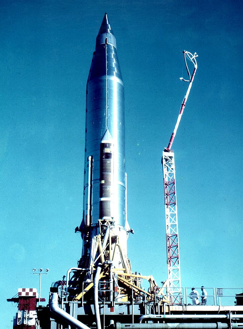
*Atlas-B with SCORE on the launch pad; the rocket (without booster engines) constituted the satellite.*
**EIRP** (Effective Isotropic Radiated Power) is the measured radiated power of an antenna in a specific direction.
For a **passive** satellite the following expression can be used to calculate the received signal power:
$$ P_{r} = \frac{P_{t} \cdot G_{t} \cdot G_{r} \cdot \sigma}{(4\pi)^{2} \cdot d_{t}^{2} \cdot d_{r}^{2}}$$
Where:
* $P_{t}, P_{r}$: Transmitter and receiver power
* $G_{t}, G_{r}$: Gain of transmitter and receiver antennas
* $d_{t}, d_{r}$: Distance of ground stations to satellite
* $\sigma$: satellite gain/loss factor
Assuming $d_{t} \approx d_{r}$ we get:
$$ P_{r} = K \cdot \frac{\sigma}{d^{4}} \cdot P_{t} $$
As we can see the received power signal is inversely proportional to the fourth power of the distance.
For an **active** satellite we get:
$$ P_{r} = \frac{P_{t} \cdot G_{t} \cdot G_{r} \cdot g_{s} \cdot A_{s}}{(4\pi)^{2} \cdot d_{t}^{2} \cdot d_{r}^{2}}$$
Where $g_{s}$ is the transponder amplification coefficient and $A_{s}$ is the effective area of the active satellite antenna. Assuming $g_{s}$ is proportional to $4\pi d_{r}^{2}$ we get:
$$ P_{r} = K^{'}\cdot \frac{A_{s}}{d^{2}} \cdot P_{t} $$
As we can see for an active satellite the received power is proportional to the second power of the distance.
*Sir Arthur Charles Clarke* was a British science fiction writer, futurist, inventor, tv host and undersea explorer. Among many other things, he is famous for being co-writer of the screenplay for 2001: A Space Odyssey. Robert Heinlein, Isaac Asimov and Arthur C. Clarke are considered by many to be the “big three” of science fiction.
You can read Extra-Terrestrial Relays [here](http://lakdiva.org/clarke/1945ww/1945ww_oct_305-308.html). It is an incredibly interesting small article that serves as proof of how Arthur C. Clark was a man ahead of his time. In this article, published in 1945, Arthur C. Clark not only explores the idea of using geostationary satellites for communication purposes but even ponders about the possibility of building a space station:
> Using material ferried up by rockets, it would be possible to construct a space-station in such an orbit. The station could be provided with living quarters, laboratories and everything needed for the comfort of its crew, who would be relieved and provisioned by a regular rocket service. This project might be undertaken for purely scientific reasons as it would contribute enormously to our knowledge of astronomy, physics and meteorology.

*Sir Arthur C. Clarke*
Over time satellite communications have been shifting towards higher and higher frequencies.
Sputnik 1 (1957 - the first satellite to orbit the earth) carried two radio beacons on frequencies of 20MHz and 40MHz. At these frequencies, amateur radio enthusiasts could easily tune into its transmissions as it passed overhead (you can listen to samples [here](https://www.youtube.com/watch?v=-YSm2qFwRpI) ). The Explorer earth orbiter missions (1958) used VHF (~100MHz). The first Lunar probe (Pioneer III) used UHF (960MHz). Over time the tendency was to increase the frequency, first to S-band (2.3 GHz) and then to X-Band (8.4GHz). The two main reasons for this was competition for frequency allocations at lower frequencies (the frequencies you can use to communicate with are tightly regulated) and the need for more spacecraft antenna directivity.
### First transatlantic optic fiber cable
It wouldn’t take too long for this prediction to come true. The **TAT-8**, constructed in 1988, was the 8th transatlantic communications cable but the first one to use optic fibers. It was capable of carrying 40,000 telephone circuits between the United States, UK and France.

*Section of the TAT-8 cable*
### Moon as relay
It is possible to use the moon as a natural communications satellite (i.e. a surface from which to bounce radio waves off). Before artificial satellites, long distance wireless communication around the curve of the earth was usually conducted by skywave transmission, in which radio waves are refracted by the Earth’s ionosphere.
The research of using the moon as a relay satellite was spun off from a military espionage program known as PAMOR (Passive Moon Relay) which sought to eavesdrop on Soviet military radar signals inadvertently reflected from the moon.